Service manual SC-150
-27-
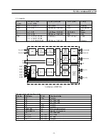
12
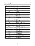
TP
In / Out
Test pin
13
TP
Out
Test pin
14
NC
Not Connected
15
TP
Out
Test pin
16
TP
Out
Test pin
17
TP
Out
Test pin
18
DVSUP
Digital power 5V
19
DVSS
Digital Ground
20
NC
Not Connected
21
NC
Not Connected
22
NC
Not Connected
23
NC
Not Connected
24
RESETQ
In
Power-On-reset
25
NC
Not Connected
26
NC
Not Connected
27
VREF2
Reference ground 2 high voltage part
28
DACM_R
Out
Loudspeaker out Right
29
DACM_L
Out
Loudspeaker out Left
30
NC
Not Connected
31
TP
Out
Test pin
32
NC
Not Connected
33
NC
Not Connected
34
NC
Not Connected
35
VREF1
Reference ground 1 high voltage part
36
SC1_OUT_R
Out
Scart output 1, right
37
SC1_OUT_L
Out
Scart output 1, left
38
NC
Not Connected
39
AHVSUP
Analog power supply 8.0V
40
CAPL_M
Volume capacitor MAIN
41
AHVSS
Analog ground
42
AGNDC
Analog reference voltage high voltage part
43
NC
Not Connected
44
NC
Not Connected
45
NC
Not Connected
46
NC
Not Connected
47
NC
Not Connected
48
ASG2
Analog Shield Ground 2
49
SC2_IN_L
In
Scart input 2 in, left
50
SC2_IN_R
In
Scart input 2 in, right
51
ASG1
Analog Shield Ground 1
52
SC1_IN_L
In
Scart input 1 in, left
53
SC1_IN_R
In
Scart input 1 in, right
54
VREFTOP
Reference voltage IF A/D converter
55
MONO_IN
In
Mono input
56
AVSS
Analog ground
57
AVSUP
Analog power supply
58
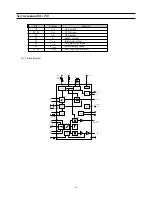
In IF input 1
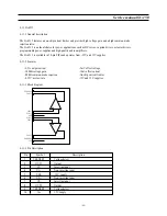
Pin No.
Pin Name
Type
Short description
Summary of Contents for CHASSIS : SC-150 Model : DSC-3220E
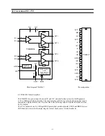
Page 35: ...Service manual SC 150 34 Block diagram TDA6107Q...
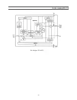
Page 44: ...Service manual SC 150 43 5 Circuit description 5 1 Block diagram...
Page 62: ...Service manual SC 150 61 5 9 2 2 STR F6654 oscillating operation...
Page 82: ...Service manual SC 150 81 8 1 PCB MAIN...
Page 83: ...Service manual SC 150 82 8 2 PCB UNION...
Page 84: ...Service manual SC 150 83 9 1 Schematic Diagram MAIN...
Page 85: ...Service manual SC 150 84 9 2 Schematic Diagram UNION...
Page 86: ......


