ENGLISH
35
9.6 Alarm
system
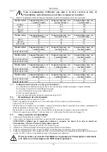
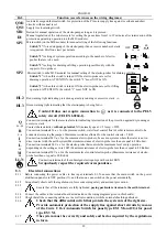
Alarm intervention is indicated by the red light ref. HL2 and at the same time by a possible remote alarm which may be
connected to the terminals ref. Q.
Test the system after installation.
Against dry operation: in the event of alarm intervention, this will continue to work even after restoration of the level; to
rest the alarm, the power supply to the panel must be disconnected.
Starts control: the alarm system will intervene 5 times, then it will be stored in the memory. At this point the alarm
must be reset by disconnecting the power supply to the panel.
9.7
Troubleshooting ES 0,75 T-ES 1 T-ES 1,5 T-ES 3 T-ES 4 T-ES 7,5 T-ES 10 T
ES 12,5 T-ES 15 T-ES 20 T-ES 25 T-ES 30 T-ES 40 T-ES 7,5 T SD-ES 10 T SD
ES 12,5 T SD-ES 15 T SD-ES 20 T SD-ES 25 T SD-ES 30 T SD-ES 40 T SD
FAULTS CHECK
(POSSIBLE
CAUSES)
REMEDY
1.
The motor is not
fed
A.
The magnetothermal switch or the differential
automatic switch on the distribution panel has
tripped..
B.
No voltage on terminals L1- L2-L3
C.
The protection of the internal transformer has
tripped.
D.
The remote control switch ref. KM1 vibrates.
E.
Check the connection of input B on the panel
and any pressure switch, level switch or other
device.
A.
Check the insulation of the pump cables. Reset
the magnetothermal switch QM1 or the
differential switch on the distribution panel.
B.
Check the panel connecting cables and any
switches or insulating switches that may have
tripped in the system.
C.
Turn off the main switch for three minutes, then
switch it on again Starting of the electropump
excludes the fault. If the electropump is not fed,
or is temporarily fed, identify any short circuits
in the secondary circuit of the transformer.
D.
The supply voltage is insufficient.
E.
Remove the fault in the electric connections.
2.
The protection
ref. QM1
intervenes.
A.
Pump impeller blocked.
B.
The motor absorption is excessive at full
load.
C.
The overload protection is faulty
A.
Carry out maintenance to free the impeller.
B.
During operation the line voltage is outside the
/- 10% of the rated voltage; or carry out
maintenance on the electropump (check the
state of the bearings)
C.
Change the component or the control unit
3.
The pump does
not deliver, the
motor does not
start, the lamp
HL2 is lit, the
lamp HL3 is off
A.
The electro-probe circuit is not efficient; the
resistance between the electro-probe lead and
the earth terminal must be < 80 k ohm
B.
The electro-probe is not immersed in the
water.
C.
The input remote control circuit at terminals
B is open.
D.
The microswitch SP1 is not correctly
positioned.
E.
The module M2S is faulty.
A.
Change the connections of the electro-probe or
the electro-probe itself. Insert the common
electro-probe connected to terminal 18 ref. I if
the water is not directly in contact with the
earth system.
B.
Position the electro-probe under the water level
C.
Close the contacts of the input remote control
circuit at terminals B, check efficiency of the
pressure switch, level switch or other device.
D.
Position the microswitch SP1 depending on the
number of the electro-probes to be used
E.
Replace the Module M2S.
4.
The pump
continues
delivering and
does not respond
to external
commands
A.
The pressure switch, level switch or other
device is not correctly connected to the
control unit.
A.
Correctly connect the pressure switch, level
switch or other device and check system
operation. If necessary, change the component.
5.
The remote
alarm is not
working
A.
The connections do not correspond to the
diagram proposed.
B.
The acoustic or luminous warnings are not
efficient.
A.
Make the connections following the diagram
proposed.
B.
Change the component.
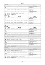
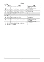
9.8
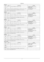
List of spare parts
ES 0,75 T
REF Code
Description
Model
QM1
002773340
MAGNETOTHERMAL SWITCH 1-1,6A
GV2-ME06 TELEMECANIQUE
140-MN-0160 AB
MS325/1,6 ABB
KM1
002773460
REMOTE CONTROL SWITCH 4 KW 400V AC3 24V 50/60Hz
LC1 D09 B7 TELEMECANIQUE
100-C09KJ10 AB
A 9-30-10 ABB
TC1
002771291
SINGLE-PHASE TRANSFORMER 0-230-400/24 30VA
BL1
002776190 MODULO
SONDE

