background image

INSTRUCTION BOOK FOR


Multi Vision Imager

Summary of Contents for Multi vision imager

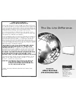
Page 1: ...INSTRUCTION BOOK FOR Multi Vision Imager ...

Page 2: ... long and will house the 6 1 4 x 8 top and bottom main frame parts the 1 1 2 x 1 1 2 frame parts hardware and wall switch The smaller cardboard box will house the side main frame parts and the fabric for the Da Snap Screen Da Snap Frame Assembly 1 Unpack the 1 1 2 x 1 1 2 frame parts and fabric from the cardboard boxes DO NOT unroll the screen surface at this time 2 Slide the frame pieces together...

Page 3: ...to the connector located on the side of junction box 7 Remove the shipping braces by removing 10 x 3 8 sheet metal screws from the aluminum slat Two of these screws will be used later to WALL MOUNT screen to wall Remove black knobs and shipping braces Carefully let the slat rest on the inside of the top frame Save the knobs they will be used to attach the Da Snap frame to the main frame 8 Carefull...

Page 4: ...ard bracket distances If your screens viewing width is under 87 wide center the single wall bracket with the frame 3 Secure large wall bracket s to wall studs at the desired height Make sure the brackets are level Drill holes and attach mounting brackets into wall You will need at least 4 clearance above the drilled holes to hang the screen It is recommended to use a 1 4 x 1 1 2 lag screws not sup...

Page 5: ...ch in center off position and allow motor to cool for 30 minutes Bracket Distances For Standard Sizes Screen Size Distance Weight 106 D HDTV 97 201 Lbs 110 D HDTV 101 207 Lbs 119 D HDTV 109 21 Lbs 133 D HDTV 121 243 Lbs 159 D HDTV 144 284 Lbs 103 D CS 100 191 Lbs 115 D CS 111 208 Lbs 125 D CS 120 223 Lbs 133 D CS 127 235 Lbs 138 D CS 131 241 Lbs 148 D CS 141 5 258 Lbs Back Lip Of Frame Will Wedge ...

Page 6: ...he splitter board Figure 6 Low Voltage Wall Switch Optional IR And RF Remote Control Motor Blue Common Brown Hot Green Ground To Case 240VAC 50Hz 240V Wiring Diagram RJ9 Up STOP DOWN Ground Must Be Connected To Building Ground RJ9 Green Front Back UP DN GND 5V 3 POSITION SWITCH RJ9 Dry Contacts Splitter UP 5V COM DN IMPORTANT NOTE The wall switch is REQUIRED to make any limit switch adjustments EV...

Page 7: ...creen is in limit set mode and no buttons are pushed for 20 seconds the LED on the back of the wall switch will turn off the motor will return to run mode and no changes will be saved If this occurs return to step 3 for down limit adjustment or step 4 for up limit adjustment IMPORTANT NOTE The wall switch is REQUIRED to make any limit switch adjustments EVEN if a third party control system is used...

Page 8: ...ircuit breaker No power to operating switch or junction Check above Tighten all loose wire connections Correct any improper connections Down Position Check for power across black and white leads Up Position Check for power across red and white leads Power at junction box Thermal overload tripped Let motor cool down for 15 minutes Try again Broken wire in the down or up position Check for continuit...

Page 9: ...9 ...

Page 10: ...10 ...

Page 11: ...11 ...

Page 12: ...HE MAXIMUM EXTENT PERMITTED BY APPLICABLE LAW THIS WARRANTY IS IN LIEU OF ALL OTHER WARRANTIES EXPRESS OR IMPLIED INCLUDING WARRANTIES AS TO FITNESS FOR USE AND MERCHANTABILITY Any implied warranties of fitness for use or merchantability that may be mandated by statute or rule of law are limited to the one 1 year warranty period This warranty gives you specific legal rights and you may also have o...

Reviews: