background image

57

D-Link DNR-202L User Manual

Section 5 - Configuration

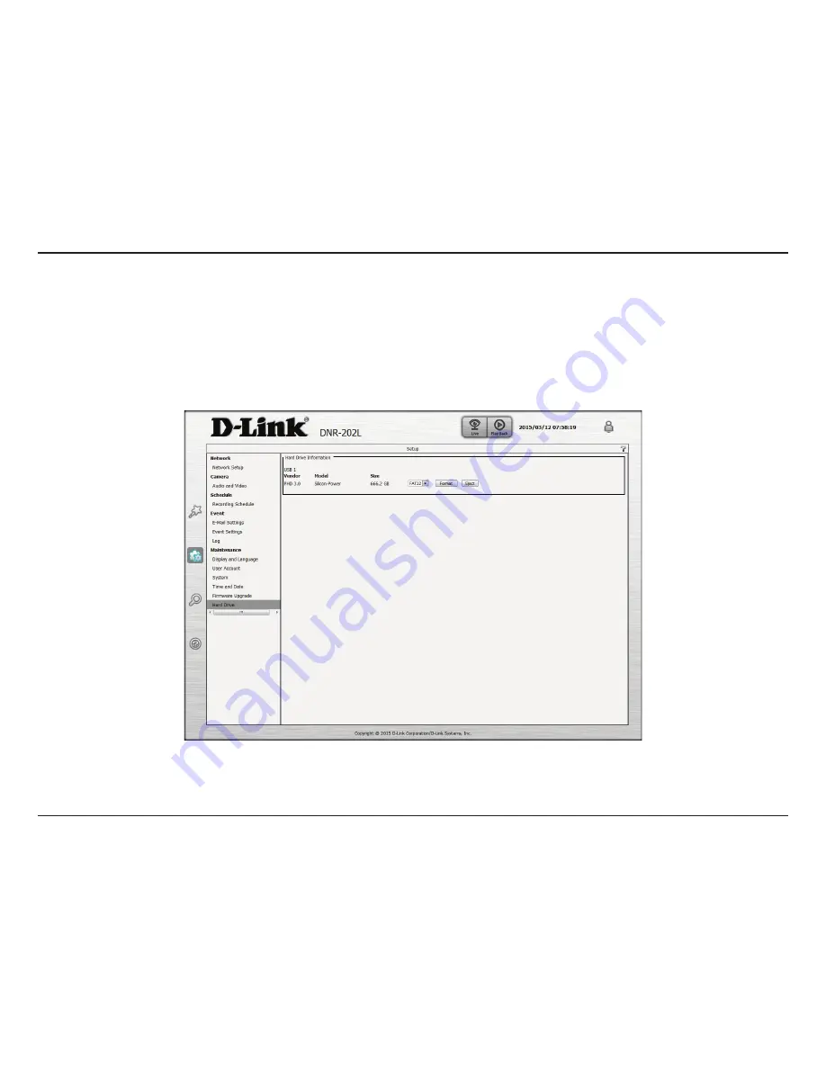
Hard Drive

The section provides users with an overview of the attached USB storage devices, and users can also format and eject attached 

USB storages devices.

Note

: All data will be erased from the attached USB storage device  during formatting.

Summary of Contents for mydlink DNR-202L

Page 1: ...User Manual DNR 202L mydlink Camera Video Recorder Version 1 20 04 01 2015 ...

Page 2: ... Description 2 0 March 13 2015 Revision A2 with firmware version 2 00 Trademarks D Link and the D Link logo are trademarks or registered trademarks of D Link Corporation or its subsidiaries in the United States or other countries All other company or product names mentioned herein are trademarks or registered trademarks of their respective companies Copyright 2015 D Link Corporation All rights res...

Page 3: ...eo 21 Playback 22 View Recording 23 Status 24 NVR Info 25 mydlink View NVR App 26 First Use Select Your Device 27 Live View 27 Video Playback 30 Video Playback Control 31 Configuration 32 Using the Configuration Interface 32 Live Video 33 Playback 37 Setup Wizard 43 Setup 46 Network Setup 46 Audio and Video 47 Recording Schedule 48 E mail Settings 49 Event Settings 50 Log 51 Maintenance 52 Display...

Page 4: ...e missing please contact your reseller Note Using a power supply with a different voltage than the one included with your product will cause damage and void the warranty for this product DNR 202L mydlink Camera Video Recorder CAT5 Ethernet cable Power adapter CD ROM with User Manual and software Quick Installation Guide ...

Page 5: ...g a PC Powered by mydlink technology the DNR 202L can be easily setup for Internet access It supports real time monitoring and playback from anywhere via an Internet browser Users can simultaneously record while viewing live feeds or while searching recordingsforplayback Completevideomanagement livesurveillance andplaybackabilitymakestheDNR 202Laconvenient and stable video recording solution Compu...

Page 6: ...feature of the DNR 202L The NVR can monitor your cameras for motion detection digital input and connection status events to trigger an action 2 Event Notification One of the most powerful functions is the notification application The NVR centrally controls the e mail notifications and can even activate a buzzer function from supported cameras Instant Live View 1 Full Screen Enlarge the display to ...

Page 7: ...s this button to release the HDD attached to the USB Port for HDD 1 5 USB Port for HDD 2 Attach an external USB HDD to this port to save recorded streams 6 HDD 2 Button Press this button to release the HDD attached to the USB Port for HDD 2 7 Auto Scan Button Press this button to automatically scan for cameras on the network 8 Reset Button Press and hold the recessed button for 10 seconds to reset...

Page 8: ... for an Internet connection Once an Internet connection is established the blue LED will blink Note If you do not connect an Ethernet cable the DNR 202L will beep Step 2 Attach an external USB HDD to the USB HDD1 port The NVR will mount the HDD and beep once Note When you want to remove an HDD press and hold the release button for at least three seconds The NVR will release the HDD and emit a long...

Page 9: ...o configure the NVR Note If the autorun program does not automatically start on your computer go to Windows and click Start Run In the Run command box type D autorun exe where D represents your CD ROM drive OS X Users Insert the DNR 202L Driver CD in the CD ROM drive After you have inserted the CD into your computer go to the CD drive directory and double click the Mac Utility folder to enter Step...

Page 10: ...anual Section 2 Installation Step 3 Connect the power adapter to the DNR 202L and then to a power outlet Click Next to continue Step 4 Connect an Ethernet cable from your router s LAN port to the DNR 202L Click Next to continue ...

Page 11: ...n 2 Installation Step 5 Make sure the LED on the NVR is lit blue then click Next to continue Step 6 The wizard will attempt to find your NVR in your network You can click Rescan to search for the DNR 202L at any time Click Next to continue ...

Page 12: ...our NVR has been found you can set a password for it in the text boxes Click Next to continue Step 8 You must format the attached hard drives for the NVR Make sure you do not have any important data on this drive before clicking Next Click OK to proceed with formatting ...

Page 13: ... You can preview the discovered cameras by clicking on the blue camera icon or click Next to continue Step 10 A pop up will ask you to enter the password for your camera Click OK The checkbox next to your camera will now have a green checkmark to indicate it has been added successfully Click Next to continue Note It is strongly advised to set up passwords for all of your cameras ...

Page 14: ...e on page 32 or click Finish Step 11 ThewizardwillguideyouthroughtheprocessofconnectingyourNVRtoamydlink account If you already have a mydlink account enter the correct configuration information and click Next to continue otherwise select I want to sign up for a newaccount orIdon twanttousemydlinkserviceand follow the instructions Click Next to continue To add cameras after initial setup refer to ...

Page 15: ... complete the installation Your DNR 202L comes with a convenient application to assist you in managing your recorded video This section will guide you through the simple setup procedure and the interface of the application Step 2 InserttheDNR 202LDriverCDintheCD ROMdrive NavigatetotheD HddViewer folder where D represents the drive letter of your CD ROM drive and double click on the setup program t...

Page 16: ...mera feed in the live video display area Actual Size Use this button to display the recording in it s native resolution Full Screen Use this button to switch to a full screen view of the live video feed On Screen Display Settings Use this button to configure the various settings for the on screen display Save as AVI Use this button to export the video as an AVI file Print Image Use option this to ...

Page 17: ... playback are highlighted in blue 3 Time Range Selection Select a beginning and end time for the recording you wish to view 4 Video Preview When Enable Preview is checked this area will display a preview 5 Timeline This timeline will adjust according to the level of zoom selected 6 Available Streams This area lists the recording devices available 7 Zoom Slider Use the zoom slider control to zoom i...

Page 18: ...l be able to remotely access your NVR from the www mydlink com website Afteryoulogintoyourmydlinkaccount youwillbetakentotheMyDevicespage To connect to your NVR click on the Connect button and provide your password to complete the login process After you have connected to the NVR you will be taken to the Live Video page Refer to Live Video on page 21 ...

Page 19: ...lue If you still cannot access your NVR reset your NVR and run the NVR Setup Wizard again from the CD ROM included in your package Here you can see the online status of each of your NVRs Your online status may be one of the following A green checkmark indicates that your NVR is online and ready to use A yellow exclamation point indicates that your NVR is online but the NVR password has changed You...

Page 20: ...Section 3 mydlink Portal Settings On the Settings tab you can see a general summary of your NVR If you wish to remove your NVR from your mydlink account click on the Delete NVR button and provide your password to complete the action ...

Page 21: ... currently recording The available controls are detailed below Control Pad This control pad can be used to pan tilt and zoom PTZ a dome camera or electronically pan tilt and zoom PTZ within the camera s predefined view area if one has been defined Zoom Control Use the and buttons to zoom in or out Actual Size Use this control to view video in it s native resolution Record Use this control to toggl...

Page 22: ...this control to open the saved recordings search dialog See View Recording on page 17 Pause Playback Use this control to pause the current playback Stop Playback Use this control to stop the current playback Step Back Forward Use these controls to pause playback and either step back one frame or advance forward by one frame Speed Down Up Use these controls to slow down or speed up the playback Zoo...

Page 23: ...beginning and end time for the recording you wish to view 3 Video Preview When Enable Preview is checked this area will display a preview 4 Timeline This timeline will adjust according to the level of zoom selected 5 Available Streams This area lists the recording devices available 6 Zoom Slider Use the zoom slider control to zoom in and out of the timeline 7 Available Recordings Recordings are gr...

Page 24: ... used storage space of the USB storage device attached to the USB 1 or USB 2 Port Unused Space This shows the amount of space available for recording on the USB storage device attached to the USB 1 or USB 2 Port Status This shows if the USB storage device attached to the USB 1 or USB 2 port is currently being recorded to Camera Status Clicking on the Camera Status button allows you to access your ...

Page 25: ...r of your device Model Name Displays the model name of your device MAC Address Displays the MAC address of your device NVR activated on Displays the time and date that your device was added to mydlink Advanced Settings Clicking on the Advanced Settings button allows you to access your NVR s configuration interface To open your NVR s configuration interface select the NVR web page and enter the pas...

Page 26: ...completed launch the mydlinkView NVR app and log in to your mydlink account Select your DNR 202L from the device list to access the live video from the connected cameras Now you can remotely access the live video playback recorded videos and manually enable or disable recording Search for mydlinkView NVR to download and install the app on your smartphone or tablet when connected to the Internet ...

Page 27: ...link account first After starting the mydlinkView NVR app your DNR 202L will be displayed in the My Device list The app will connect to your DNR 202L and you can then view live video and playback from your recordings archive via your device First Use Select Your Device Tap on the DNR 202L icon and the mydlink View NVR will access the Live video panel Live View ...

Page 28: ...st of your mydlink account iPhone iPod touch Grid View On an iPhone or an iPod touch mydlink View NVR can display the Device List of your mydlink account on the main screen Tap on your DNR 202L to enter the 4 grid view iPad Grid View On an iPad mydlink View NVR can expand and shrink the Device List of your mydlink account at the left hand side of the panel Tap on your DNR 202L to enter the live vi...

Page 29: ...mode you can tap on the video stretch button to stretch the video to full screen Tap the button again to disable stretch Note This function may alter the aspect ratio of the video stream Snapshot While streaming a single channel tap the Snapshot button to capture a snapshot The image will be saved to the device s picture storage area While viewing video in grid view tap the Snapshot button to take...

Page 30: ...e mail button to capture a snapshot of all the channels and insert all the snapshots into a single e mail Complete the To Cc BccfieldsasrequiredandtapSend tosendthee mailwithsnapshotattached or tap Cancel to cancel the operation Video Playback The video playback function is only available in single view mode Tap the open recording button while in single channel mode to bring up the playback select...

Page 31: ...ackcontrol button to control the direction of the video playback The control buttons are Step backward for 1 Second Play pause toggle Step forward for 1 Second Use the speed panel to control the speed of video playback from x1 through to x32 speed Note The quality of display performance will vary according to network bandwidth availability ...

Page 32: ...gure your DNR 202L At the end of the wizard click Go to NVR or enter the IP address of your NVR into a web browser such as Internet Explorer To log in use the username admin and the password you created in the Setup Wizard If you did not create a password the default password is blank After entering your password click OK Step 2 Enter your NVR credentials to access the configuration interface Step...

Page 33: ...nually customize your NVR s network camera schedule events and maintenance settings 3 Camera Search This takes you the camera settings page where you can add cameras and customize your camera settings 4 Help This takes you to the help section in the UI 5 Channel Windows You can drag to reposition camera streams or double click to view one stream The selected video stream will be marked with a red ...

Page 34: ...he selected camera s microphone if camera supports audio When enabled you can adjust the volume via the slider 14 Live Playback Switch between the Live View and the Playback pages 15 Log In Out Click this to log in or out of the NVR 16 Info Sections This section contains various detailed information about the NVR You can collapse or restore each section for viewing by clicking on the title bar Not...

Page 35: ...Go to Preset Select a preset from the drop down list to apply it to the camera Preset Name Enter a name for the selected Preset Set as Preset Click to apply the selected Preset Once you have set a preset you can enable Patrol and Auto Pan modes System Information The system information section displays basic statistics and details about the NVR server Click on the title bar to collapse this sectio...

Page 36: ...rage information section displays details of free space and used space on the attached USB hard drive Log The log section displays detailed messages about your System NVR and Events Click the respective dial to isolate the category and click Previous or Next to navigate between pages ...

Page 37: ...ayback Controls These buttons allow you to Step Backward Rewind Play Pause Speed Up and Step Forward the video Click Rewind or Speed Up more than once to increase the rate of playback 3 Playback Speed This is the current speed of playback either forward or in reverse 4 Volume Bar Click on the speaker icon to mute unmute and use the bar to adjust the volume 5 Seek Bar You can drag on the bar to jum...

Page 38: ...rent video stream and save it Event List The system information section displays basic statistics and details about the NVR server Click on the title bar to collapse this section Calendar The calendar displays days when recordings were made as indicated by a highlight You can navigate to the day month and year of your choice Clicking on a highlighted date will open the View Recorded Files window ...

Page 39: ...time for the recording you wish to view 3 Video Preview When Enable Preview is checked this area will display a preview 4 Timeline This timeline will adjust according to the level of zoom selected 5 Available Streams This area lists the recording devices available 6 Zoom Slider Use the zoom slider control to zoom in and out of the timeline 7 Available Recordings Recordings are graphed below the ti...

Page 40: ...ing types from each other This will help you select video clips Step 3 Select a time period using the Start Time and End Time in the Date Time Period section Alternatively select a range from the timeline Step 4 Select the Enable Preview option to get a preview of the video you select Step 5 Highlight the video clip s you would like to review by left clicking and dragging the time period in the ti...

Page 41: ...format Step 1 During playback users can choose the camera from which they would like to save a video clip Step 2 Set the cue in and cue out points the cue in and cue out time will be shown on the information window Then click the Video Export button Step 3 Click Browse and choose the folder where you would like to save the file Step 4 Select the export options Step 5 Click the OK button 2 5 3 4 1 ...

Page 42: ... Save Snapshot During playback users can choose to save an image from a selected camera Step1 ClicktheSnapshotbuttonwhenthedesiredimageisshownonthescreen Step 2 Choose the folder to save the file in Step 3 Click OK to save the image to that location 1 2 3 ...

Page 43: ...NR 202L User Manual Section 5 Configuration Use this tab if you want to follow the simple steps of the Setup Wizard Click the Wizard icon to begin the Setup Wizard Setup Wizard Click Next to begin the Setup Wizard ...

Page 44: ...our network connection type Select Static IP if your Internet Service Provider has provided you with connection settings or if you wish to set a static address within your home network Note SelectDHCPifyouareunsureofwhichsettingstochoose Click Next to continue STEP 2 Choose your time zone from the drop down menu Click Next to continue ...

Page 45: ...er Manual Section 5 Configuration STEP 4 Enter a name and description for your device Click Next to continue STEP 5 Click Finish to complete the setup process Please wait a few moments while the DNR 202L saves your settings ...

Page 46: ...estinations in a different subnet Invalid gateway settings may cause the failure of transmissions to a different subnet Primary domain name server that translates names to IP addresses Secondary domain name server to backup the primary one Under Static IP enable or disable the DHCP server If your network doesn t have a DHCP server enable NVR DHCP server for easier local network setup You can confi...

Page 47: ...mera supports Select the frame rate Select the resolution Select the bit rate Select the image quality Check the Enable Audio option for live view and recording Click to connect to the web page of the selected network camera for advanced setup For example motion detection should be configuredviathecamerawebinterfacetoenabletheNVRtoreceive the trigger message Step 3 Click the Save Settings button N...

Page 48: ...ra to record after the event is recorded Select this and drag on the calendar below to specify times for continuous recording Select this and drag on the calendar below to specify times for recording only when events occur Enable Scheduled Recording Enable Audio Recording Enable Automatic Overwrite Pre record Post record Continuous Recording Record On Event On this page set the recording schedule ...

Page 49: ...he SMTP port of the sender s server Check the box if it requires a secure connection Click this button to send a test e mail Enter a username for the recipient Enter the email address for the recipient Click Add to add the recipient to the list Sender Email Address Server Address User Name Password Port Test Contact User Name Contact Email Address Set the email configuration on this page to receiv...

Page 50: ...ly event and event actions to specific channels This option allows you to receive notifications when the hard drive space if full on the attached USB drive This option allows you to receive notifications when the attached hard drive has an error This option allows you to receive notifications when the NVR connection to your network is lost Enable buzzer and e mail notifications by checking the cor...

Page 51: ...ink DNR 202L User Manual Section 5 Configuration Log This page displays the system NVR and event messages of your NVR You can click Download to save the logs to a text file and click Clear to delete the logs ...

Page 52: ...enus Enter the name of the NVR Enter a time for auto scanning of IP cameras in your network Tick to show the OSD on the stream Tick to show the camera name on the OSD Tick to show the camera number on the OSD Tick to show the date on the OSD Tick to show the time on the OSD Tick to show the bit rate on the OSD Tick to show the frame rate on the OSD Select from the drop down the size of the OSD inf...

Page 53: ...a user name from the list and click to delete the account Tick to allow viewing the channels and using PTZ control in live mode Tick to allow viewing the channels and exporting recorded video in playback mode Tick to allow the user to use Setup Manual backup and Speaker functions Note The Administrator account can configure all functions of the NVR This account cannot be deleted The default passwo...

Page 54: ...ttings Idle Time Minutes Buzzer Enable Auto Plugin Click to reboot the NVR Click Restore to reset all configurations to factory default settings Save the configuration settings to your computer Browse your computer for configuration settings to be loaded into the NVR Set the time in minutes for system idle Turn on or off the buzzer Enable or disable auto plugin ...

Page 55: ...ually This uses the time settings from your computer to apply the NVR time settings Enable this feature to obtain time automatically from an NTP server NetworkTimeProtocol NTP synchronizestheDNR 202L with an Internet time server Choose the one that is closest to your location Select your time zone from the drop down menu Select this to enable daylight saving time Select this option to allow your c...

Page 56: ...firmware can be upgraded from this page The firmware update must be saved on the local hard drive of your computer Click the Browse button to search the local hard drive for the firmware update file Click Load to upgrade You may check for firmware updates on the D Link Support website ...

Page 57: ...uration Hard Drive The section provides users with an overview of the attached USB storage devices and users can also format and eject attached USB storages devices Note All data will be erased from the attached USB storage device during formatting ...

Page 58: ...illautomatically searchforallcompatiblecamerasonthesamenetwork Once it is detected in the top left window click on the camera to highlight it and its information will be displayed on the bottom right Step 2 Enter the User Name and Password of the selected camera Step 3 Select a channel from the Add to Channel drop down menu Step 4 Click Add and the selected camera will be added to the Camera List ...

Page 59: ...sed by the IP camera Enter the user name of the IP camera Enter the password of the IP camera Select the IP camera vendor from the drop down list Select the IP camera model from the drop down list Select the channel from 1 4 that you want the camera to stream to Click this button to update changes made to the camera settings Click this button to automatically detect camera information Click this b...

Page 60: ...0 D Link DNR 202L User Manual Section 5 Configuration Help This section describes configuring and viewing live video from your network cameras the functions of the live video screen and the PTZ functions ...

Page 61: ...rite HDD2 Key Trigger Method Description USB1 button Press button for 3 seconds Un mount HDD1 Buzzer will beep long USB1 LED off USB2 button Press key2 for 3 seconds button Un mount HDD2 Buzzer will beep long USB2 LED off Auto scan button Auto scan function Press scan button for 3 seconds Start auto scan IP Cameras in local network Buzzer will beep long Camera Echo function Press scan button for 0...

Page 62: ...ution 1280 x 720 1 channel 640 x 480 4 channels LiveView Display Modes 1 and 4 channels display Recording Modes Schedule Manual Event Motion Continuous Recording Performance 32 Mbps Playback Modes Time Event Camera Playback Performance Max 720p for 1 channel 640 x 480 4 channels Playback Control Play Stop Pause Forward Backward Next Previous Video Export Formats AVI Network Physical Interface RJ45...

Page 63: ...agement Take snapshots video via web browser Configuration interface accessible via web browser System Log Status of active users Login history Certifications CE FCC CE LVD C Tick Physical Weight 90 grams External Power Adapter Input Min 0 5V 2 5 A Consumption 8 5 watts 5 include 2 x 2 5 HDD Temperature Operating 0 to 40 C Storage 20 to 70 C 4 to 158 F Humidity Operating 10 to 90 non condensing St...

Page 64: ...e user is encouraged to try to correct the interference by one of the following measures Reorient or relocate the receiving antenna Increase the separation between the equipment and receiver Connect the equipment into an outlet on a circuit different from that to which the receiver is connected Consult the dealer or an experienced radio TV technician for help Non modifications Statement Any change...

Page 65: ...is equipment is a label that contains among other information a product identifier of 0 If requested this number must be provided to the telephone company 2 If this equipment 0 causes harm to the telephone network the telephone company will notify you in advance that temporary discontinuance of service may be required But if advance notice isn t practical the telephone company will notify the cust...

Page 66: ...alarm equipment consult your telephone company or a qualified installer Safety Warning CAUTION Risk of Explosion if Battery is replaced by an Incorrect Type Dispose of Used Batteries According to the Instructions ATTENTION Risque d explosion si la batterie est remplacée par un type incorrect Jetez les piles usagées selon les instructions Industry Canada Statement This device complies with Industry...

Page 67: ...nt This equipment should be installed and operated with minimum distance 20 cm between the radiator your body Déclaration d exposition aux radiations Cet équipement est conforme aux limites d exposition aux rayonnements IC établies pour un environnement non contrôlé Cet équipement doit être installé et utilisé avec un minimum de 20 cm de distance entre la source de rayonnement et votre corps Warni...

Page 68: ...功能 低功率射頻電機之使用不得影響飛航安全及干擾合法通信 經發現有干擾現象時 應立即停用 並改善至無干擾時方 得繼續使用 前項合法通信 指依電信法規定作業之無線電通信 低功率射頻電機須忍受合法通信或工業 科學及醫療用電波輻射性電機設備之干擾 無線傳輸設備 UNII 在 5 25 5 35 秭赫頻帶內操作之無線資訊傳輸設備 限於室內使用 無線資訊傳輸設備忍受合法通信之干擾且不得干擾合法通信 如造成干擾 應立即停用 俟無干擾之虞 始得繼續使 用 無線資訊傳設備的製造廠商應確保頻率穩定性 如依製造廠商使用手冊上所述正常操作 發射的信號應維持於操作頻 帶中 電磁波曝露量MPE標準值 MPE 1 mW cm2 送測產品實值為 0 mW cm2 電池警語 廢電池請回收 ...

Page 69: ...nd EFTA countries except in France where restrictive use applies This device may not be used for setting up outdoor radio links in France and in some areas the RF output power may be limited to 10 mW EIR P in the frequency range of 2454 2483 5 MHz For detailed information the end user should contact the national spectrum authority in France This equipment may be operated in AL AD BE BG DK DE FI FR...

Page 70: ...eloupe Martinique St Pierre et Miquelon Mayotte 2454 2483 5 MHz 100 mW indoor 10 mW outdoor Reunion et Guyane 2400 2483 5 MHz 100 mW Rest of EU community 2420 2483 5 MHz 100 mW R TTE 1999 5 EC WLAN 2 4 2 4835 GHz IEEE 802 11b g n Spectrum Regulation MHz Europa ETSI max EIRP Innenbereich max EIRP Außenbereich Europa 2400 2483 5 MHz 100 mW 100 mW Frankreich 2400 2454 MHz 100 mW 100 mW 2454 2483 5 MH...

Page 71: ... 5 875 Ghz Channels 36 40 44 48 149 153 157 161 165 169 Austria 5 15 5 35 GHz Channels 36 40 44 48 52 56 60 64 France 5 15 5 35 5 47 5 725 GHz Channels 36 40 44 48 52 56 60 64 100 104 108 112 116 120 124 128 132 136 140 Denmark Germany Iceland Finland Netherlands Norway Poland Sweden Slovenia Luxembourg U K Ireland Slovak Switzerland Hungary Italy 5 15 5 35 Ghz 5 725 5 875 Ghz Channels 36 40 44 48...

Page 72: ... Spanish PormediodelapresenteD LinkdeclaraqueelDNR 202Lcumpleconlosrequisitosesenciales y cualesquiera otras disposiciones aplicables o exigibles de la Directiva 1999 5 CE Ελληνική Greek ΜΕΤΗΝ ΠΑΡΟΥΣΑ D Link ΔΗΛΩΝΕΙ ΟΤΙ DNR 202L ΣΥΜΜΟΡΦΩΝΕΤΑΙ ΠΡΟΣΤΙΣ ΟΥΣΙΩΔΕΙΣ ΑΠΑΙΤΗΣΕΙΣ ΚΑΙ ΤΙΣ ΛΟΙΠΕΣ ΣΧΕΤΙΚΕΣ ΔΙΑΤΑΞΕΙΣ ΤΗΣ ΟΔΗΓΙΑΣ 1999 5 ΕΚ Français French Par la présente D Link déclare que l appareil DNR 202L e...

Page 73: ...i postanowieniami Dyrektywy 1999 5 EC Português Portuguese D Link declara que este DNR 202L está conforme com os requisitos essenciais e outras disposições da Directiva 1999 5 CE Slovensko Slovenian D Link izjavlja da je ta DNR 202L v skladu z bistvenimi zahtevami in ostalimi relevantnimi določili direktive 1999 5 ES Slovensky Slovak D Link týmto vyhlasuje že DNR 202L spĺňa základné požiadavky a v...

Page 74: ...e Doing so can cause a fire or an electrical shock by shorting out interior components The powering of this device must adhere to the power specifications indicated for this product Do not overload wall outlets and or extension cords as this will increase the risk of fire or electrical shock Do not rest anything on the power cord or on the device unless the device is made and expressly approved as...

Page 75: ...efore connecting the power cable to the power supply Unplug the power cable before removing the power supply If the system has multiple sources of power disconnect power from the device by unplugging all power cables from the power supplies Servicing Disassembling Do not service any product except as expressly set forth in your system documentation Opening or removing covers that are marked with t...

Page 76: ...painted metal surface on the chassis You can also take the following steps to help prevent damage from electrostatic discharge ESD 1 When unpacking a static sensitive component from its shipping carton do not remove the component from the antistatic packing material until you are ready to install the component in your system Just before unwrapping the antistatic packaging be sure to discharge stat...

Page 77: ...e about our environmentally responsible products and packaging please visit www dlinkgreen com DEUTSCH DE Dieses Symbol auf dem Produkt oder der Verpackung weist darauf hin dass dieses Produkt gemäß bestehender örtlicher Gesetze und Vorschriften nicht über den normalen Hausmüll entsorgt werden sollte sondern einer Wiederverwertung zuzuführen ist Bringen Sie es bitte zu einer von Ihrer Kommunalbehö...

Page 78: ...s et faiblement toxiques tant dans ses produits que ses emballages D Link recommande de toujours éteindre ou débrancher vos produits D Link lorsque vous ne les utilisez pas Vous réaliserez ainsi des économies d énergie et réduirez vos émissions de CO2 Pour en savoir plus sur les produits et emballages respectueux de l environnement veuillez consulter le www dlinkgreen com ESPAÑOL ES Este símbolo e...

Page 79: ...nti e dei propri prodotti Allo scopo di ridurre al minimo tale impatto D Link progetta e realizza i propri prodotti in modo che rispettino il più possibile l ambiente utilizzando materiali riciclabili a basso tasso di tossicità sia per i prodotti che per gli imballaggi D Link raccomanda di spegnere sempre i prodotti D Link o di scollegarne la spina quando non vengono utilizzati In questo modo si c...

Page 80: ...które odpowiednie do tego celu podmioty przyjmą takie produkty nieodpłatnie dlatego prosimy dostarczyć go do punktu zbiórki wskazanego przez lokalne władze Poprzez proces recyklingu i dzięki takiemu postępowaniu z produktem oraz jego opakowaniem pomogą Państwo chronić środowisko naturalne i dbać o ludzkie zdrowie D Link i środowisko W D Link podchodzimy w sposób świadomy do ochrony otoczenia oraz ...

Page 81: ...a adrese www dlinkgreen com MAGYAR HU Ez a szimbólum a terméken vagy a csomagoláson azt jelenti hogy a helyi törvényeknek és szabályoknak megfelelően ez a termék nem semmisíthető meg a háztartási hulladékkal együtt hanem újrahasznosításra kell küldeni Kérjük hogy a termék élettartamának elteltét követően vigye azt a helyi hatóság által kijelölt gyűjtőhelyre A termékek egyes helyeken ingyen elhelye...

Page 82: ...rmasjon angående våre miljøansvarlige produkter og forpakninger kan du gå til www dlinkgreen com DANSK DK Dette symbol på produktet eller emballagen betyder at dette produkt i henhold til lokale love og regler ikke må bortskaffes som husholdningsaffald mens skal sendes til genbrug Indlever produktet til et indsamlingssted som angivet af de lokale myndigheder når det er nået til slutningen af dets ...

Page 83: ... Toimimalla näin autat säästämään energiaa ja vähentämään hiilidioksiidipäästöjä Lue lisää ympäristöystävällisistä D Link tuotteista ja pakkauksistamme osoitteesta www dlinkgreen com SVENSKA SE Den här symbolen på produkten eller förpackningen betyder att produkten enligt lokala lagar och föreskrifter inte skall kastas i hushållssoporna utan i stället återvinnas Ta den vid slutet av dess livslängd...

Page 84: ...rma ajuda a preservar o ambiente e protege a saúde humana A D Link e o ambiente Na D Link compreendemos e comprometemo nos com a redução do impacto que as nossas operações e produtos possam ter no ambiente Para minimizar este impacto a D Link concebe e constrói os seus produtos para que estes sejam o mais inofensivos para o ambiente possível utilizando meteriais recicláveis e não tóxicos tanto nos...

Reviews: