background image

DWR-500 Quick Installation Guide 


DWR-500 Operating Range  


Operating Temperature Range 

-40°C  ~  +55°C 

Storage Temperature Range 

-40°C  ~  +80°C 

Non-Condensing Humidity Range 

10%  ~  90% 

Wind Survivability Rating 

> 165mph 

Power input (VAC) 

110/240  (50/60 Hz) 

AC Power Consumption 

5W (typical) – 30 W (Maximum) 

Table 1. DWR-500 Operating Range 


DWR-500 Environmental Rating 


Ingress Protection (IP) Rating 

66 

Shock and Vibration Rating 

ETSI 300-19-2-4 spec T41.E class 4M3 

Table 2. DWR-500 Environmental Rating 
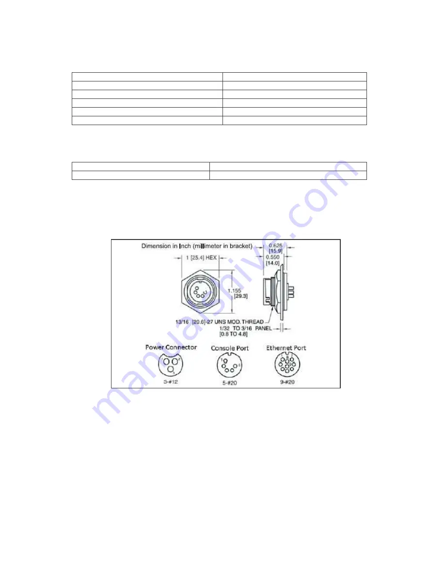
 

Connector ports  


Figure 2 shows the Ethernet port, Console port and Power cable connector. Radio Port 0 and Port 1 are 

standard N-type female connectors. 


Figure 2. Power cable connector, console port and Ethernet port 


DWR-500 Connection Interfaces  


As the DWR-500 is equipped for outdoor coverage, the connection interfaces needs to be insulated against 

the weather. Appended are information on the various interfaces used by the DWR-500: 


Ethernet Cable  

Figure 3 shows one end of the Ethernet cable for connecting to the port on the DWR-500, and the other 

end of the cable with a normal RJ45 jack. Between the two cable connectors in the diagram shows the pin 

mapping. 


Summary of Contents for DWR-500

Page 1: ...D Link Quick Installation Guide DWR 500 Wireless Mesh Router Quick Installation Guide Version 1 5 5 January 30 2007 ...

Page 2: ... Corporation reserves the right to make changes to products described in this document without notice D Link Corporation does not assume any liability that may occur due to the use or application of the product s described herein Standards This device complies with Part 15 of the FCC Rules Operation is subject to the following two conditions 1 this device may not cause harmful interference and 2 t...

Page 3: ...s near antenna installation site Take extreme caution when installing antennas Do not to come into contact with power lines or electrical circuits as they can cause serious injury or death Grounding Warning Always ground the equipment before power up The required resistance must be less than 5 ohm between the ground termination points to grounding tier Power Socket Installation Warning Power socke...

Page 4: ...talling The Solar Shield 5 Securing The DWR 500 On Mast 7 Installing The DWR 500 On Wall 7 Grounding The DWR 500 7 Connecting The DWR 500 To Ethernet 8 Connecting The Power Cable To DWR 500 8 Installing The Lightning Protector 9 Administrating The DWR 500 10 COMMAND LINE INTERFACE ACCESS 10 IP BASED ACCESS 10 DWR 500 Basic Configuration 11 USING THE QUICK SETUP WIZARD 12 EXAMPLE CONFIGURATION 1 PO...

Page 5: ...ion of the DWR 500 Further Reading More detailed configuration instructions can be found in the CD ROM Before You Begin Open the shipping carton and carefully unpack its contents The packing list is as shown below Please ensure all items are present and undamaged If any of the items is found missing or damaged please contact your local D Link representative as soon as possible Package Contents ITE...

Page 6: ...ross subnet roaming High scalability Self discovery of neighbor nodes Auto disaster recovery End to end QoS support Reliable and secure Hardware Introduction Figure 1 shows the connectors on the DWR 500 Wireless Mesh Router Figure 1 DWR 500 and the location of the connectors For safe installation and operation it is recommended that you Visually inspect the power cord and ensure it is secured full...

Page 7: ...al Rating Connector ports Figure 2 shows the Ethernet port Console port and Power cable connector Radio Port 0 and Port 1 are standard N type female connectors Figure 2 Power cable connector console port and Ethernet port DWR 500 Connection Interfaces As the DWR 500 is equipped for outdoor coverage the connection interfaces needs to be insulated against the weather Appended are information on the ...

Page 8: ...de Function Pin Mapping White Yellow Ground Pin 1 Red Live Pin 2 Black Green Neutral Pin 3 Figure 4 Power cable connector for DWR 500 Console Cable The weather insulated end of the console cable is shown on the left in the Figure 5 The right shows the pin mapping The other end of the console cable to connect to the laptop has a normal DB9 connector Figure 5 Console Cable Connector and DB9 connecto...

Page 9: ...t item 2 solar shield item 3 and DWR 500 With the screws provided place the installation bracket item 2 onto the solar shield item 3 Secure the installation bracket with the screws and nuts as shown in Figure 8 Figure 8 Tighten the nuts to secure the installation bracket There are 2 ways to secure the installation bracket This is dependent on the direction of the mast If the mast is horizontal sec...

Page 10: ...Secure the DWR 500 onto the solar shield at the side with the screws provided as seen in Figure 11 Figure 11 Secure DWR 500 onto the Solar Shield Secure the screws at the top of the DWR 500 to the solar shield as shown in the left and center diagrams of Figure 12 The diagram on the right of Figure 12 shows the DWR 500 setup with solar shield and installation bracket Figure 12 Secure DWR 500 to the...

Page 11: ... and the installation bracket onto the expansion bolts Fasten the nuts to secure the DWR 500 to the wall as shown in Figure 14 Figure 14 Wall mounted DWR 500 Grounding the DWR 500 DWR 500 must be grounded before power up Grounding wire resistance must be less than 5 ohm The DWR 500 must be grounded to prevent electrostatic damage The grounding terminal is at the side of the DWR 500 The grounding c...

Page 12: ...t Ethernet cable to Ethernet port Connecting the Power Cable to DWR 500 Installation of power source must be done by trained electrician DWR 500 must be grounded before power up The antennas should be setup before connecting the power source to DWR 500 Please refer to the respective antenna installation guide for further instructions The power terminal is located on the left side of the DWR 500 Co...

Page 13: ...00 Installing the Antenna Feeder Cable Feeder cable is used to connect the antenna with DWR 500 The feeder is kept as short as possible to reduce loss of signal strength If a longer feeder cable is required it is recommended to use a thicker feeder cable to reduce the loss The table below shows the typical pass loss of 100m feeder cable Figure 20 N male to N male Antenna Cable Feeder Type Cable lo...

Page 14: ...hown in Table 4 The login details are in Table 5 Baud Rate 115200 Data Bits 8 Parity None Stop Bits 1 Flow Control None Table 4 Terminal setting Figure 22 Connect console cable to DWR 500 IP Based Access The DWR 500 default IP address is 192 168 0 1 with subnet mask of 255 255 255 0 on port 0 To access the DWR 500 administration set the connecting computer to a static IP address in the same subnet...

Page 15: ...information is authenticated the user friendly and intuitive web based administrative GUI will be displayed as shown in Figure 25 and access will be granted for setting up the DWR 500 Figure 25 Web based administrative GUI DWR 500 Basic Configuration The following steps assume that the backhaul will be automatically detected and configured once the DWR 500 is setup The instructions shown here are ...

Page 16: ... will complete the configuration Figure 27 Quick Setup to configure DWR 500 1 Node ID can be any integer 1 and 255 and must be unique within a single mesh network 2 Router ID is an IPv4 loopback address that identifies the router and is usually the best way to connect to the administration functions of an operational router must be unique within a single mesh network 3 This is the IP address and n...

Page 17: ... as Portal See Figure 28 Figure 28 Step 1 setting up Portal Node Step 2 Shown in Figure 29 enter the Router ID IP Address Mask Ethernet Gateway and enable NAT as per the Table 7 Figure 29 Step 2 Setting up router details for Portal Node Step 3 Shown in Figure 30 enter the SSID and the DNS information and the Portal Node setup is complete Hit the Finish button to complete the setup Figure 30 Step 3...

Page 18: ...plete Example Configuration 2 Point node Step 1 Select the country where DWR 500 will be installed Based on Figure 26 and Table 7 point node is assigned as 2 Finally select the role of this node as Point See Figure 32 Figure 32 Step 1 Setting up a Point Node Step 2 Shown in Figure 33 enter the Router ID IP Address Mask as per the Table 7 Figure 33 Step 2 Setting up router details for Point Node ...

Page 19: ...ortal Node Setup Example Configuration 3 AP node Step 1 Select the country where DWR 500 will be installed Based on Figure 26 and Table 7 AP node is assigned as 2 Finally select the role of this node as AP See Figure 35 Figure 35 Step 1 Setting up a AP Node Step 2 Shown in Figure 36 enter the Router ID IP Address Mask as per the Table 7 Figure 36 Step 2 Setting up router details for Point Node ...

Page 20: ...tup is completed each of the DWR 500 will automatically discover other nodes and form a wireless mesh network The portal node should have an Ethernet connection Both the portal and AP will then be able to service clients and access the Internet through the portal Note The scope of this document does not cover tuning the mesh network for total coverage For more detailed configuration instructions p...

Reviews: