background image


47 


Technical Support 

You can find software updates and user documentation on the D-
Link website.  

D-Link provides free technical support for customers within the
United States and within Canada for the duration of the warranty 
period on this product.  

U.S. and Canadian customers can contact D-Link technical support 
through our website, or by phone. 


Tech Support for customers within the United States: 

D-Link Technical Support over the Telephone: 

(877) 453-5465 

Monday through Friday 6:00am to 6:00pm PST  

D-Link Technical Support over the Internet: 

http://support.dlink.com 

e-mail: 

[email protected]


Tech Support for customers within the Canada: 

D-Link Technical Support over the Telephone: 

(800) 361-5265 

Monday through Friday 7:30am to 9:00pm EST 

D-Link Technical Support over the Internet: 

http://support.dlink.ca 

e-mail: 

[email protected]


Summary of Contents for DWL-P1012 - Power Injector - 185 Watt

Page 1: ...DWL P1012 12 Port Web Smart IEEE 802 3af Power over Ethernet Midspan Version 1 01 User s Guide ...

Page 2: ......

Page 3: ...acking 3 Setup 4 Installing the DWL P1012 on a Desktop 4 Installing the DWL P1012 on a Rack 5 Connecting Network Cables 6 Power on 7 Identifying External Components 8 Front Panel Components 8 Rear Panel 9 LED Indicators 10 System LED 10 PoE Port Status LED 11 Management Port Status LED 11 Configuration 12 Installing the Web Management Utility 12 ...

Page 4: ...lbar 16 Configuring the DWL P1012 17 Login 17 Setup Menu 20 SNMP Setting 21 PoE Setting 25 Schedule 27 Port Group 29 SNTP 31 Device Status 32 System Setting 35 RTC Time 36 Trap Setting 38 Set Password 39 Backup Setting 39 Reset Setting 39 Logout 40 WARRANTY 41 ...

Page 5: ...l rear panel and LED indicators of the Midspan Configure the Midspan Configuration of the smart functions of the Midspan through the web interface Warranty Warranty information and FCC Declaration INTRODUCTION The DWL P1012 Power over Ethernet Midspan injects power into data carrying Ethernet cabling The Midspan will add power to 12 ports respectively in a 10 100BASE TX Ethernet network over TIA E...

Page 6: ...ort circuit protection per channel Standard 19 inch rack mountable Ports Data ports upper row of ports Twelve 12 10 100Mbps Fast Ethernet data input ports These ports are designed to carry Ethernet data only Tx Rx over the standard 2 wire pairs pins 1 2 and 3 6 PoE ports lower row of ports Twelve 12 10 100Mbps Fast Ethernet with 48V DC power output ports These ports are designed to carry Ethernet ...

Page 7: ...e DWL P1012 and carefully unpack its contents The carton should contain the following items One DWL P1012 Web Smart PoE Midspan Four rubber feet with adhesive backing One AC power cord Mounting kit two brackets and screws CD ROM This User s Guide and Utility If any item is found missing or damaged please contact your local reseller for replacement ...

Page 8: ...span in a fairly cool and dry place for the acceptable temperature and humidity operating ranges Install the Midspan in a site free from strong electromagnetic field generators such as motors vibration dust and direct exposure to sunlight When installing the Midspan on a level surface attach the rubber feet to the bottom of the device The rubber feet cushion the Midspan protect the casing from scr...

Page 9: ...d 19 rack Use the following diagrams to guide you Fasten the mounting brackets to the DWL P1012 using the screws provided With the brackets attached securely you can mount the DWL P1012 in a standard rack as shown on the following page Mounting the DWL P1012 in a Standard 19 Rack ...

Page 10: ... The data outputs from the switch are connected to the Midspan The Midspan delivers power over spare twisted pairs pins 7 8 and pins 4 5 of the Category 5 cabling without degrading the quality of data communications The Management port may be connected directly or through a LAN to the Management station ...

Page 11: ...x when connected to the DWL P1012 IEEE 802 3af compliant Power Source Equipment will not energize the unused pairs unless an 802 3af compliant Powered Device signals the Power Source Equipment that it is ready to receive power Power on The DWL P1012 must be used with AC power sources 100 240 VAC 50 60 Hz The DWL P1012 s power supply will adjust to the local power source automatically Plug one end ...

Page 12: ... port LED Indicators Comprehensive LED indicators that display the conditions of the DWL P1012 and status of the network A description of these LED indicators follows Reset button The Reset button is to reset all device settings back to factory defaults Note The Midspan supports PoE port priority management When the available system power is less than required by the PD the Midspan will enforce Po...

Page 13: ...standard three pronged connector that supports the AC power cord Plug in the female connector of the provided power cord into this socket and the male side of the cord into a power outlet The DWL P1012 automatically adjusts its power setting to any supply voltage in the range from 100 240 VAC at 50 60 Hz ...

Page 14: ...powered on to indicate the ready state of the device Off When the Midspan is powered off or the power cord has an improper connection Power Maximum PWR MAX On When the PoE remaining system power 15 4W system power consumption 185W the system will not provide power to any additional PoE PD inserted Off When the system has enough remaining power greater than 15 4W CPU Blinking When the CPU is workin...

Page 15: ...il Off No PoE powered device PD connected or device is unplugged from the PoE output port Management Port Status LED Link Act green On When the Link Act LED lights on the respective port is successfully connected to an Ethernet network Blinking When the Link Act LED is blinking the port is transmitting or receiving data on the Ethernet network Off No link 100M green On When the respective port is ...

Page 16: ... Autorun From the Autorun menu select the option to install the utility Skip to step 4 If the Menu does not automatically appear go to the Start menu on the Windows desktop then choose Run 3 In the Run dialog box type D Web Management Utility setup exe D depends where your CD Rom drive is located and click OK 4 Follow the on screen instructions to install the utility 5 Upon completion go to Progra...

Page 17: ...utton to transfer a device from the Discovery List to the Monitor List System Term definitions in the Discovery List MAC Address Shows the device MAC Address IP Address Shows the current IP address of the device Protocol version Shows the version of the Utility protocol Product Name Shows the device product name System Name Shows the appointed device system name Location Shows where the device is ...

Page 18: ...pointed device system name Location Shows where the device is located Trap IP Shows the IP where the Trap to be sent Subnet Mask Shows the Subnet Mask set of the device Gateway Shows the Gateway set of the device View Trap The Trap function can receive and display the events that issue SNMP traps from the DWL P1012 in the Monitor List There is an indicator light on the View Trap button When this i...

Page 19: ...ate Trap IP and Trap Events first Device Setting You may configure the device by using the function key in the Device Setting Dialog box Configuration Setting In the Configuration Setting you may configure the IP Address Subnet Mask Default Gateway Set Trap to Trap Host IP Address System name and Location Select the device in the Discovery list or Monitor List and press this button then the Config...

Page 20: ...ately Firmware Upgrade If D Link releases firmware to support new functions the new firmware can be uploaded through here Web Access Double click the device in the Monitor List or select a device in the Monitor List and press the Web Access button to access the device through a Web browser Toolbar The toolbar in the Web Management Utility have four main tabs File View Options and Help ...

Page 21: ...ces are Refresh Time function this function helps you to refresh the time of monitoring the device Select 15 seconds 30 seconds 1 min 2 min and 5 min to configure the time of monitoring In the Help TAB there is an About function it will show the version of the Web Management Utility Configuring the DWL P1012 The DWL P1012 has a Web GUI interface for smart function configurations The DWL P1012 may ...

Page 22: ... http 192 168 0 1 the factory default IP address setting in the address bar location Alternatively through the Web Management Utility you do not need to remember the IP Address simply select the device shown in the Monitor List of the Web Management Utility to access the device through a Web Browser When the following dialog page appears enter the default password admin and press Login to access t...

Page 23: ...19 ...

Page 24: ...on the left side of the screen see Below Click on the setup item that you want to configure or monitor There are eight options SNMP PoE Schedule Port Group SNTP Status System RTC Time Trap Password Backup Settings and Reset Settings as shown in the Main Menu screen ...

Page 25: ...MP defines both the format of the MIB specifications and the protocol used to access this information over the network The DWL P1012 supports SNMP version 1 In SNMP v 1 user authentication is accomplished using community strings which function like passwords The remote user SNMP application and the DWL P1012 SNMP must use the same community string SNMP packets from any station that have not been a...

Page 26: ...MIB as an extended Management Information Base The proprietary MIB may also be retrieved by specifying the MIB Object Identifier MIB values can be either read only or read write Enabled Disabled To enable or disable the SNMP function of the DWL P1012 SNMP Community Trap To configure the SNMP Community or SNMP Trap Host Configure SNMP Community Add Group To add an SNMP Community group press Add Gro...

Page 27: ...p and configure its community name and community enable Press Apply to save the changes to the SNMP Community Group Configure SNMP Trap Trap authentication fail When checked the Midspan will issue an SNMP Trap in the event of a failed login attempt Add Trap To create a recipient of SNMP traps generated by the DWL P1012 s SNMP agent press Add Trap button In the SNMP Trap Set window fill in the comm...

Page 28: ...wer off a trap when the PoE port s power is on and down Power over current a trap when the PoE port s power is over current Power short circuit a trap when the PoE port s power circuit was short Power threshold above below a trap when the Midspan s system usage over 80 or below from 80 the system power budget Delete Trap To delete a previously defined SNMP Trap Press the Delete Trap button In the ...

Page 29: ...he PoE Setting screen shows the status of all PoE ports including PoE Enable Power limit Power current Watt Power Voltage V Power current mA Classification Status System budget power Support total power Remainder Power The ratio of system power supply Note The PoE Status information of Power current Power Voltage and Current are instantaneous values Please Refresh the browser window to renew the i...

Page 30: ...le or disable the PoE function Power limit This function allows one to manually set a port power current limitation to be given to the PD to protect the DWL P1012 and the connected device the power limit function will disable the PoE function of the port when the power is over loaded Select 5W 10W 14W and Auto for the power limit Auto will follow the classification from the PD for power current ...

Page 31: ...Midspan will enforce PoE port priority management the numerically lower port number will have a higher priority than the numerically higher port number Port 1 Port 2 Port 12 Schedule The DWL P1012 is capable of enabling and disabling power to each port based on a recurring schedule that may be defined using the Schedule page of the Web UI Scheduling must be used in conjunction with Port Grouping i...

Page 32: ...ithout begin and end date restrictions Active From Configure the begin date and time of the schedule profile only applies to Time Setting schedule profiles Active To Configure the end date and time of the schedule profile only applies to Time Setting schedule profiles Day Time Grid Select the hours during which the PoE port should be active during each day of the week respectively The first checkb...

Page 33: ...e This allows system administrators to control when their PoE equipment is powered on or off by the hour seven days a week Each port may only be a member of a single group to change a ports group memebership first remove it from its current group then add it to the destination group To add a new group click Add Group To modify an existing group click on the corresponding ID number Description Ente...

Page 34: ...30 Click Delete Group to remove an entire group Select the check box next to the group to be deleted and click Apply to remove ...

Page 35: ...the list of NTP servers used to synchronize Select SNTP Time Zone DST to configure the Time Zone the midspan is located in and enable Daylight Savings Time if desired To add a time server IP or DNS name click Add Server Server IP Enter an IPv4 address or Fully Qualified Domain Name of a time server with which the midspan will update Click Apply to save To remove a time server from the list click D...

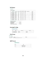
Page 36: ...splay the device status on this screen it will show the System Status SNMP Settings PoE Status Schedule Profiles Port Grouping SNTP Server and Daylight Savings Time info This page will load upon a successful login to the WebUI System Status SNMP Settings ...

Page 37: ...33 PoE Status Schedule Profiles Port Group SNTP Server ...

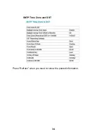
Page 38: ...34 SNTP Time Zone and DST Press Refresh when you need to renew the posted information ...

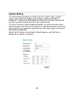
Page 39: ... device by using the System Name and the Location Name The Login Timeout for the management interface is to set the idle time out for security reasons when there is no activity for the specified period of time during a log in session the session will expire and you must log in again to access the Web based Configuration Specify the IP Address Subnet Mask Default Gateway and DNS Server address for ...

Page 40: ...gure the System Time select the year month and day from the appropriate drop down Select the hour in 24 hour notation minute and second and click the Set Time button to apply the changes To use the time and date of the PC from which you are configuring the Midspan select PC Time from the drop down menu The time and date from the computer being used to configure the DWL P1012 will automatically upd...

Page 41: ...ime and date select SNTP Time from the drop down menu The DWL P1012 will then contact the first SNTP server in the time server list in a top down order to update the system time The correct time should appear in the appropriate fields Click the Set Time button to apply changes ...

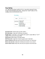
Page 42: ...trap when booting up the system Illegal Login a trap when a wrong password is used in a login attempt The IP address of the source will be recorded PoE Events Monitoring the PoE ports status PoE Power fail a trap when the port s power source has failed Power on Power off a trap when the PoE port s power is on and down Power over current a trap when the PoE port s power is over current Power short ...

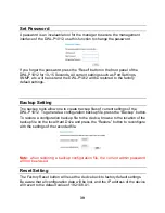
Page 43: ...create backup files of current settings of the DWL P1012 To generate a configuration backup file press the Backup button To restore a configuration backup file to the device browse to the location of the backup file on the local Hard Drive and press the Restore button to reconfigure with the settings of the recorded file Note when restoring a backup configuration file the current admin password wi...

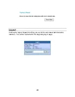
Page 44: ...40 Logout Clicking the logout Hyperlink will log you out of the web based administrative interface You will be redirected to the beginning log in page ...

Page 45: ... obligation shall be to repair or replace the defective Hardware during the Warranty Period at no charge to the original owner or to refund at D Link s sole discretion Such repair or replacement will be rendered by D Link at an Authorized D Link Service Office The replacement Hardware need not be new or have an identical make model or part D Link may in its sole discretion replace the defective Ha...

Page 46: ...determines in its sole discretion that it is not practical to replace the non conforming Software the price paid by the original licensee for the non conforming Software will be refunded by D Link provided that the non conforming Software and all copies thereof is first returned to D Link The license granted respecting any Software for which a refund is given automatically terminates Non Applicabi...

Page 47: ...es prepaid Expedited shipping is available if shipping charges are prepaid by the customer and upon request D Link may reject or return any product that is not packaged and shipped in strict compliance with the foregoing requirements or for which an RMA number is not visible from the outside of the package The product owner agrees to pay D Link s reasonable handling and return shipping charges for...

Page 48: ... OF THE PRODUCT INCONVENIENCE OR DAMAGES OF ANY CHARACTER WHETHER DIRECT SPECIAL INCIDENTAL OR CONSEQUENTIAL INCLUDING BUT NOT LIMITED TO DAMAGES FOR LOSS OF GOODWILL LOSS OF REVENUE OR PROFIT WORK STOPPAGE COMPUTER FAILURE OR MALFUNCTION FAILURE OF OTHER EQUIPMENT OR COMPUTER PROGRAMS TO WHICH D LINK S PRODUCT IS CONNECTED WITH LOSS OF INFORMATION OR DATA CONTAINED IN STORED ON OR INTEGRATED WITH...

Page 49: ...g this Product may be reproduced in any form or by any means or used to make any derivative such as translation transformation or adaptation without permission from D Link Corporation D Link Systems Inc as stipulated by the United States Copyright Act of 1976 Contents are subject to change without prior notice Copyright 2005 by D Link Corporation D Link Systems Inc All rights reserved CE Mark Warn...

Page 50: ... equipment does cause harmful interference to radio or television reception which can be determined by turning the equipment off and on the user is encouraged to try to correct the interference by one or more of the following measures Reorient or relocate the receiving antenna Increase the separation between the equipment and receiver Connect the equipment into an outlet on a circuit different fro...

Page 51: ...rt through our website or by phone Tech Support for customers within the United States D Link Technical Support over the Telephone 877 453 5465 Monday through Friday 6 00am to 6 00pm PST D Link Technical Support over the Internet http support dlink com e mail support dlink com Tech Support for customers within the Canada D Link Technical Support over the Telephone 800 361 5265 Monday through Frida...

Reviews: