Building Networks for People
DVS-104 User Manual v1.00
- 8 -
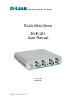
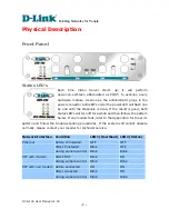
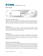
BNC video inputs “IN” & outputs “OUT”
Video Server allows up to four cameras attached at the same time. To ensure video
modulation type being detected correctly, cameras should be attached sequentially from
“VIDEO1” to “VIDEO4” and powered on before Video Server is powered on. There are
also four loop-through connectors of video outputs for conjunction with other capturing
devices like time-lapsed VCR. In such case, read the next paragraph for correct settings.
DIP switches “1” to “4”
There are four DIP switches numbered from “1” to “4” in the front panel regarding of
each video input. They are used to enable the 75-ohm resistance of video impedance.
They should be kept ON if there is only one camera connected to each video input. If
users want to connect another device such as VCR or multiplexer to the video output, the
switch should be turned up to disable the impedance.
Auxiliary buttons “CLEAR” & “RESET”
There are two buttons located at the center of the front panel, one is labeled “CLEAR”
and the other is labeled “RESET”. Refer to the Appendix Troubleshooting for the detailed
usage of system recovery.
Summary of Contents for DVS-104
Page 6: ...Building Networks for People DVS 104 User Manual v1 00 ...
Page 57: ...Building Networks for People DVS 104 User Manual v1 00 55 ...
Page 111: ...Building Networks for People DVS 104 User Manual v1 00 109 ...
Page 112: ...Building Networks for People DVS 104 User Manual v1 00 110 ...
Page 113: ...Building Networks for People DVS 104 User Manual v1 00 111 ...

