background image

33

Web-based Management (continued)

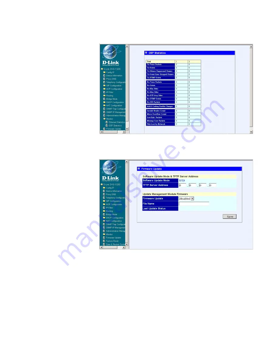
Monitor - DSP Statistics

This window displays
a variety of DSP
statistics.

Firmware Update

Software Update
Mode -


Image files

down through TFTP.

TFTP Server
Address -


 The IP

Address of the TFTP
server where the
runtime or
configuration file is
located. This entry is
used only if the
Firmware Update is
set to 

Enable.

Firmware Update -


 Determines whether or not the device will try to look

for a runtime image file on the TFTP server.

File Name -


 The complete path and filename of the runtime image file on

your TFTP server to be uploaded to the device.

Last Update Status -


 This is a read-only field that displays the Update

Status.

Click 

Save

 to save the settings.

Summary of Contents for DVG-1120S - VoIP Gateway/Router With 1 LAN Port

Page 1: ...VoIP Residential Gateway with Two Voice Ports Manual Building Networks for People D Link DVG 1120S ...

Page 2: ...ions 5 Features and Benefits 6 LEDs 7 Web based Management 8 Configuration Using a Console 35 Using the Console Port 40 Command Line Interface 46 Networking Basics 54 Technical Specifications 69 Contacting Technical Support 72 Warranty 73 Registration 76 ...

Page 3: ...ts For Configuration Package Contents At least 128 MB of memory and a 500 MHz processor Computer with Windows Macintosh or Linux based operating system with an installed Ethernet adapter Internet Explorer or Netscape Navigator version 4 0 or above with JavaScript enabled Note Using a power supply with a different voltage rating than the one included with the DVG 1120S will cause damage and void th...

Page 4: ...reate a home or small office LAN network The built in DHCP server and Network Address Translation NAT function automatically assigns IP addresses for LAN users allowing multiple users to share a single Internet connection You can configure and monitor the DVG 1120S via the Console or the Web browser Telnet and SNMP management is also supported By routing calls over the Internet or any IP network t...

Page 5: ...al port of a PC running a terminal emulation program such as Microsoft HyperTerminal or a VT 100 terminal Phone 1 to 2 Normal RJ 11 phone jacks used to connect telephones and fax machines Plug your normal telephone s and or fax machine directly into any of these jacks Line RJ 11 phone jack for connecting to a standard telephone wall outlet through an approved No 26 AWG or larger telecommunications...

Page 6: ... sharing to allow multiple users to access the Internet via a single IP address Built in PPPoE function to support dial up connection for broadband technology Supports Caller ID Supports QoS to guarantee voice quality Automatic Call Redirection ACR function support PSTN or VoIP line automatic selection e g 110 119 PSTN VoIP routing table support Call will automatically redirect to PSTN in case of ...

Page 7: ...sually a Cable or ADSL Modem When a good link to a powered up but idle device is detected on a port the WAN indicator shines steadily When packets are received from the device the indicator blinks off and on Phone 1 to 2 This LED displays the PSTN status and Hook Ringing activity on the RJ 11 port that is used to connect to your normal telephone s fax machine and PSTN line Power This LED is lit wh...

Page 8: ... the LAN port by entering the IPAddress into your web browser address field Initially the VoIP gateway does not have a Username or Password To log in simply click on the OK button After logging in the Device Info screen on the following page will be displayed Click on Login to the Web based Management module 192 168 15 1 Type 192 168 15 1 the IP Address into the address field of your browser http ...

Page 9: ...s default IP To configure the WAN port please do the following Then go to Start Control Panel Network Connections Right click local area connection select Properties double click Internet Protocol TCP IP The screen at right will appear Make sure the PC is in the same IP domain as the VoIP gateway You can do this by changing the IP Address of the PC as shown here Click on Config WAN IP Address Manu...

Page 10: ...uthentication Password Enter the Password for the PPPoE function Confirm Password Enter the Password again for confirmation More WAN IP Configuration settings include Manual When Manual is chosen the VoIP gateway will obtain its IP settings from the fields located just below BOOTP When BOOTP is chosen the VoIP will attempt to obtain its IP settings from a BOOTP server located on your WAN DHCP When...

Page 11: ...device Boot PROM Version The version number of the device s startup code Firmware Version The version number of the device s runtime code DSP Version The Digital Signal Processor version if any Serial Number A user determined identification number System Name A user defined name for this device Country Code A user defined country code for this device 0 USA Default 1 Japan 2 Hong Kong 3 Sweden 4 Ch...

Page 12: ...12 Web based Management continued Proxy DNS State Enables or disables the Proxy DNS function Proxy DNS IP Address Enter the Proxy DNS IP Address Click Save to save the settings ...

Page 13: ... tone phones TEL Dial Signal Set the dial signal of telephone Echo Cancel Enable or disable the Echo Canceller function VAD This is used to enable or disable the VAD Voice Activity Detector function Digital Timer A user defined digital interval timer to determine the end of user dialing Hook Flash Set the hook flash timer Default 700 ms Dial Pulse Set the dial pulse value of the analog phone Defau...

Page 14: ...P server User Parameter Enable or disable the user phone parameter in SIP URL Timer T2 The user defined T2 timer of SIP protocol Range 4 8 16 32 sec Initial Unregister Enable or disable this function Register Expiration Enter the expiration time Session Expires Enter the session expiration Min SE Enter the Min SE time Session Expires Refresher Choose uac or uas Click on the Save button at the bott...

Page 15: ... ID Delivery Enable or disable this function Display CID Enable or disable the Caller ID display function User Agent Port A user defined unique port number for each phone port Authentication Username Enter the Username for SIP server authentication Authentication Password Enter the Password for SIP server authentication Confirm Password Enter the Password again for confirmation Click on the Save b...

Page 16: ... support Peer to Peer communication Index Choose the index number that you would like to edit From 1 to 10 Phone Number This is a user defined phone number for the destination endpoint User IP Address Enter the phone number and IP Address of the destination endpoint Format Destination Phone number Destination IP Address X X X X Port Enter the port number of the destination endpoint Click Save to s...

Page 17: ...d below Voice Default Line Choose and setup the default line through VoIP or PSTN Conditions under which a VoIP Call would automatically be redirected to PSTN 4xx 5xx 6xx Error Message Enable or disable the automatic redirection of a VoIP call to PSTN whenever the 4xx 5xx 6xx error message is received from the SIP server No Response Against Invite Enable or disable the redirection of the call to P...

Page 18: ...l store all the digits and forward them to the non default line Click the Edit icon on the window above to access the second ACR Configuration window shown below Index Choose the index number that you would like to edit From 1 to 30 Number This is a user defined telephone number that you would like to call using VoIP or PSTN There are three kind of number formats that can be used 2nd window ACR Co...

Page 19: ...tal and it means a random number e g 55T The system will transmit all of the numbers that begin with 55 to the non default line Ex 553 5551 557 5555 etc Del Digit Enter the number of digits that will be deleted from the front of the number when the system transmits the number above Ex The number is 505 555 5555 Del Digit is 3 System will only transmit 555 5555 Click on the Save button at the botto...

Page 20: ...ndow After you have clicked on an edit icon this window will appear Type in an appropriate identifying comment for the IP Filter set For more editing options click the icon once again and the 3rd IP Filter window will appear When you are finished defining the rules for each set select enabled or disabled to enable or disable the listed filtering sets Click the Edit icon on the window above to acce...

Page 21: ...e Subnet Mask to pass or block packets destined to that IP Address Port Filter Rule UDP and TCP packets only Select a range of ports to pass or block Use the following guide to define the port or port range Start Port and End Port Web based Management continued 3rd IP Filter window Specifies the port numbers less than and equal to the Start Port number Specifies the port numbers greater than and e...

Page 22: ...se RIPv1 RIPv2 or On both versions for the LAN and WAN interface To disable both versions of RIP select Off Click on the Save button at the bottom right of the window to save the settings Routing Static Route Configuration Use Static Routing to specify a route used for data traffic within your WAN or LAN This can be used to specify that all packets destined for a particular subnet use a predetermi...

Page 23: ...e specified subnet or device Interface Select WAN or LAN Interface Metric Type in the maximum number of hops allowed for the static route State Enable of disable the route Click on the Save button at the bottom right of the window to save the settings Click on the Clear button at the bottom right of the window to clear the settings Static Route Configuration 2nd window Bridge Mode To enable Bridge...

Page 24: ...me This specifies the amount of time in hours a client can lease an IP Address from the dynamically allocated IP pool DNS1 2 Server IP This specifies the Domain Name System server used by the DHCP clients to translate host names into IP Addresses or vice versa WIN Server IP Some LANs may require using WINS servers enter the IP Address of the WINS server or leave blank Domain Name Enter a domain na...

Page 25: ...the window above to access the second Static IP Assignment window Static IP Assignment 2nd window The items in this window are described below Index Choose the index number that you would like to edit From 1 to 4 MAC Address This specifies the physical address of the particular host that will receive the IPAddress IP Address This is the static IP Address to be assigned All other parameters Netmask...

Page 26: ...ve the settings NAT Configuration NAT Configuration NAT Configuration Local Server Configuration This window allows you to view the current local server configuration settings Click the Edit icon on the window above to access the second Local Server Configuration window shown on the next page continued on next page ...

Page 27: ...bal Port Enter the designated TCP or UDP protocol port number for the particular protocol packet you wish to redirect Local Port Enter the port number used by the designated host on the LAN or use a well known port Server IP Enter the IP Address of the local designated host computer or device State Disable or Enable the Local Server Configuration function Click Save to save the settings ...

Page 28: ... each other Click the Edit icon on the window above to access the second Dynamic NAT window Index Choose the index number that you would like to edit From 1 to 6 Global IP Start Enter the starting global IP Address Global IP End Enter the ending global IP Address Local IP Start Enter the starting local IP Address Local IP End Enter the ending local IP Address State Select Disable or Enable Dynamic...

Page 29: ... is valid on the Internet or on the same subnet of the global interface State Select Disable or Enable Static NAT function Click Save to save the settings Web based Management continued NAT Configuration Static NAT This window allows you to view the current Static NAT settings when Static NAT is chosen Click the Edit icon on the window above to access the second Static NAT window shown below Stati...

Page 30: ... name SNMP AuthTrap Enable or disable the SNMP trap Click Save to save the settings SNMP IP Management Address This window supports two SNMP manager IP Addresses for accessing this device and only these managers can manage this device IP Address 1 Enter the first SNMP manager IP Address IP Address 2 Enter the Second SNMP manager IP Address Click Save to save the settings ...

Page 31: ...vice Rx Bytes The total number of bytes contained in packets received by the device Rx Non Ucast Packets The number of non unicast packets received by the device Rx Discard Packets The number of packets dropped by the device Rx Frame Too Long The number of packets that are larger than the 1514 Ethernet packet limit Rx Non Aligned Errors The number of packets that are not aligned properly Rx Collis...

Page 32: ... The number of non unicast packets sent Tx Discard Packets The number of packets dropped by the device Tx Heartbeat Errors The number of heartbeat errors This relates to an internal timing function Tx Late Collision The number of late collisions Tx Retransmission Limit The number of times the device had to retransmit packets Tx Underrun Packets This counter shows the number of runt packets transmi...

Page 33: ...ntime or configuration file is located This entry is used only if the Firmware Update is set to Enable Firmware Update Determines whether or not the device will try to look for a runtime image file on the TFTP server File Name The complete path and filename of the runtime image file on your TFTP server to be uploaded to the device Last Update Status This is a read only field that displays the Upda...

Page 34: ...e device Note After performing the Factory Reset make sure to redefine the IP settings for the device Then perform a Save Restart System on the device After these procedures are performed your Factory Reset is complete After the settings have been saved to NV RAM they will become the default settings for the device and they will be used every time it is powered on reset or rebooted The only except...

Page 35: ...e or b an ordinary RS 232 cable and a null modem adapter One end of the cable or cable adapter combination must have a 9 pin D shell connector suitable for the Diagnostics port the other end must have a connector suitable for the console s serial communications port 2 Power down the devices attach the cable or cable adapter combination to the correct ports and restore power 3 Set the console to us...

Page 36: ...onnecting to the device First Time Connecting to the VoIP Gateway First make the console connection to the device and then power it on If your terminal or terminal emulation program is properly configured according to the specifications defined above you will see the POST test and the boot up process After the process is completed you will see the window shown be low Initially the VoIP gateway has...

Page 37: ...37 Configuration Using a Console First Time Connecting to the VoIP Gateway Configuration Commands You can type nwdbg to see all of the configuration commands Shown Below ...

Page 38: ...Console Configuration Commands Configure IP This 192 168 0 1 command line allows you to enter the related commands for the inital configuration of this device Type nwdbg ipgw to show the IP setting of th edevice default is PPoE ...

Page 39: ...BNET MASK set device subnet mask to d d d d nwdbg gw GATEWAY IP set device default gateway to d d d d nwdbg lan_ip x x x x set LAN IP Address nwdbg lan_mask x x x x set LAN IP MASK Type nwdbg ip manual to setup your device s WAN IP to manual mode After you have finished type nwdbg save changes to save your settings and re start the device The following window will appear Now your device s WAN IP i...

Page 40: ... is being used You need a RJ 14 to RS 232 converter RJ 14 and RS 232 cable Please see the previous section for additional information Next power the de vice on by simply plugging it in You will see the boot up process After the process is complete you will see the window shown below Initially the VoIP gateway has a default Username and Password admin To log in enter admin for the username and pass...

Page 41: ...41 Using the Console Port Configuration Commands You can type nwdbg and press Enter to see all of the configuration com mands Shown below ...

Page 42: ...iguration Commands The 192 168 0 1 command line allows you to enter the related commands for the initial configuration of this device Configure IP Type nwdbg ipgw and press Enter to show the IP setting of the device default is PPPoE ...

Page 43: ... d d nwdbg mask SUBNET MASK set device subnet mask to d d d d nwdbg gw GATEWAY IP set device default gateway to d d d d nwdbg lan_ip x x x x set LAN IP Address Type nwdbg ip manual to setup your device s WAN IP to manual mode After you have finished type nwdbg save changes to save your settings and re start the device The following window will appear Now your device s WAN IP is in manual mode with...

Page 44: ...P ADDRESS set the IP address of TFTP server tftp get FILENAME get the remote image file if FILENMAE is not specified the image file name in EEPROM will be employed tftp update update the image in flash Console mode TFTP Update Firmware Commands Screen After you have finished the firmware upgrade type the nwdbg system reboot command on the 192 168 0 1 command line and press Enter The following wind...

Page 45: ...ctory reset on the 192 168 0 1 command line and press Enter The following window will appear Console mode nwdbg Factory Reset Command Screen Once the reset is done all of the device s settings stored in NV RAM will be erased and restored to values present when the device was purchased The firmware upgrade procedure is complete ...

Page 46: ...se All command line examples in this chapter are in bold type Listed below are some of the most commonly used commands parameter s and examples of their usage General Setup Commands nwdbg system reboot Definition This command is used to restart the device Parameter s None Example nwdbg system reboot nwdbg save changes Definition This command is used to save the configuration changes into flash mem...

Page 47: ...un 123456789012 nwdbg pw PASSWORD Definition This command sets the password if there is a password string or shows the username password if only nwdbg pw is typed Parameter s PASSWORD maximum string length is 12 characters Example nwdbg pw nwdbg slic 0 1 Definition This command changes the Subscriber Line Interface Circuit SLIC state to standby or active or shows the SLIC state if only nwdbg slic ...

Page 48: ...DDRESS the format is XX XX XX XX XX XX Example nwdbg mac 00 50 ba 08 24 56 nwdbg ip dhcp bootp manual Definition This command sets the software boot mode to DHCP BOOTP or Manual mode If only nwdbg ip is typed this command shows the IP configuration DHCP While the system is booting the system acts as a DHCP client BOOTP While the system is booting the system acts as a BOOTP client This mode is used...

Page 49: ...BNET MASK Definition This command sets the fixed subnet mask which is used as the system s subnet mask if the software boot mode is Manual mode If only nwdbg mask is typed this command shows the IP configuration Parameter s SUBNET MASK Example nwdbg mask 255 0 0 0 nwdbg gw GATEWAY IP Definition This command sets the fixed GW address which is used as the system s GW address if the software boot mod...

Page 50: ... If only nwdbg lan_ip is typed this command shows the LAN IP configuration Parameter s IP ADDRESS Example nwdbg lan_ip 10 1 1 120 nwdbg lan_mac MAC ADDRESS Definition This command sets the LAN MAC address or shows the LAN address if only nwdbg lan_mac is typed Parameter s MAC ADDRESS the format is XX XX XX XX XX XX Example nwdbg lan_mac 00 50 ba 08 24 56 nwdbg dns DNS IP Definition This command se...

Page 51: ...ting interface to config the tone frequency for different country If only nwdbg country is typed this command shows the COUNTRY CODE Parameter s 0 USA Default 1 Japan 2 Hong Kong 3 Sweden Example nwdbg country 1 nwdbg gain RX GAIN TX GAIN Definition This command sets the receive and transmit gain or shows the RXGAIN TX GAIN state if only nwdbg gain is typed Parameter s RX TX GAIN Range 14 to 13dB ...

Page 52: ...ds between two echo requests Example ping 10 1 1 6 n 100 w 2 i 1 Command Line Interface General Setup Commands TFTP Client Setup Commands When the user enters tftp the screen will show all commands about the TFTP client ggdbg tftp tftp srvip IP ADDRESS set the IP address of TFTP server tftp get FILENAME get the remote image file If FILENAME is not specified the image file name in EEPROM will be em...

Page 53: ...FILENAME is the name of the image on the TFTP server If any error occurs during the image download the message ERROR will be displayed When the user enters tftp get the file name in EEPROM will be employed Example ggdbg tftp get c 102nmm tfp Download d project dg102 102nmm tfp OK tftp update Definition This command updates the image in FLASH The image is downloaded for storage in DRAM If any error...

Page 54: ...osoft Windows XP Note Please refer to websites such as http www homenethelp com and http www microsoft com windows2000 for information about networking computers using Windows 2000 ME or 98 Go to Start Control Panel Network Connections Select Set up a home or small office network Networking Basics When this screen appears Click Next ...

Page 55: ...ns in this window Networking Basics continued Click Next In the following window select the best description of your computer If your computer connects to the internet through a gateway router select the second option as shown Click Next ...

Page 56: ...56 Enter a Computer description and a Computer name optional Networking Basics continued Click Next Enter a Workgroup name All computers on your network should have the same Workgroup name Click Next ...

Page 57: ... while the Network Setup Wizard applies the changes Networking Basics continued When the changes are complete click Next Please wait while the Network Setup Wizard configures the computer This may take a few minutes ...

Page 58: ...ion that fits your needs In this example Create a Network Setup Disk has been selected You will run this disk on each of the computers on your network Click Next Insert a disk into the Floppy Disk Drive in this case drive A Format the disk if you wish and click Next ...

Page 59: ...e s how in the screen below After you complete the Network Setup Wizard you will use the Network Setup Disk to run the Network Setup Wizard once on each of the computers on your net work To continue click Next Please wait while the Network Setup Wizard copies the files ...

Page 60: ...w settings will take effect when you restart the computer Click Yes to restart the computer You have completed configuring this computer Next you will need to run the Network Setup Disk on all the other computers on your network After run ning the Network Setup Disk on all your computers your new wireless net work will be ready to use ...

Page 61: ...you wish this field is optional To rename the computer and join a domain Click Change Networking Basics continued Naming your Computer To name your computer in Windows XP please follow these directions Click Start in the lower left corner of the screen Right click on My Computer Select Properties and click ...

Page 62: ...ve the same Workgroup name Click OK Checking the IP Address in Windows XP The wireless adapter equipped computers in your network must be in the same IP Address range see Getting Started in this manual for a definition of IP Ad dress Range To check on the IP Address of the adapter please do the following Right click on the Local Area Connection icon in the task bar Click on Status ...

Page 63: ... Protocol technology If you are using a DHCP capable Gateway Router you will not need to assign Static IP Addresses If you are not using a DHCP capable Gateway Router or you need to assign a Static IP Address please follow these instructions Go to Start Double click on Control Panel Networking Basics continued Checking the IP Address in Windows XP This window will appear Click the Support tab Clic...

Page 64: ...64 Networking Basics continued Assigning a Static IP Address in Windows XP 2000 Double click on Network Connections Double click on Properties Right click on Local Area Connections ...

Page 65: ...r D Link wireless routers have a LAN IP address of 192 168 0 1 In the window below select Use the following IP address Input your IP address and subnet mask The IP Addresses on your network must be within the same range For example if one computer has an IP Address of 192 168 0 2 the other computers should have IP Addresses that are sequential like 192 168 0 3 and 192 168 0 4 The subnet mask must ...

Page 66: ...Go to the Apple Menu and se lect System Preferences Click on Network Select Built in Ethernet in the Show pull down menu Select Manually in the Configure pull down menu Input the Static IP Ad dress the Subnet Mask and the Router IP Ad dress in the appropriate fields Click Apply Now ...

Page 67: ...h OSX Go to the Apple Menu and se lect System Preferences Click on Network Select Built in Ethernet in the Show pull down menu Select Using DHCP in the Configure pull down menu Click Apply Now The IP Address Subnet mask and the Router s IP Address will appear in a few seconds ...

Page 68: ...r or Access Point A good wireless connection will show four replies from the Wireless Router or Access Point as shown Checking the Wireless Connection by Pinging in Windows Me and 98 Go to Start Run type command A window similar to this will appear Type ping xxx xxx xxx xxx where xxx is the IP Address of the Wireless Router or Access Point A good wireless connection will show four replies from the...

Page 69: ...t MDI II LAN NWay 10 100BASE TX Fast Ethernet ports MDI X IEEE 802 3 10BASE T Ethernet compliance IEEE 802 3u 100BASE TX Fast Ethernet compliant Quality of Service Voice service is prioritized over the data traffic FAX support V 21 V 27ter V 29 V 17 Modulation Demodulation Network Protocols TCP IP UDP ARP ICMP TFTP Telnet SNMP HTTP RIP1 RIP2 DHCP Dynamic Host Configuration Protocol server and clie...

Page 70: ...lenge Handshake Authentication Protocol PAP CHAP Administrative password through Web Telnet and SNMP Packet filter by IP Address port number and protocol LEDs General Power Status Alarm Ethernet WAN Link Act LAN 10 100M Link Act Phone 1 to 2 PSTN VoIP Hook Ringing Dimensions 6 78 W x 6 165 D x 1 339 H 172mm x 156 6mm x 34mm Number of Ports One 10BASE T Ethernet port WAN One 10 100BASE TX Fast Ethe...

Page 71: ...fications continued Power Supply AC to DC power adapter provided DC Input 12VDC 1A Operating Temperature 0 50 C Storage Temperature 10 55 C Humidity 5 95 non condensing Safety UL CUL Emission EMI FCC part 68 VCCI Class B ...

Page 72: ...adian customers can contact D Link technical support through our website or by phone Tech Support for customers within the United States D Link Technical Support over the Telephone 877 453 5465 24 hours a day seven days a week D Link Technical Support over the Internet http support dlink com email support dlink com Tech Support for customers within Canada D Link Technical Support over the Telephon...

Page 73: ...tware portion of the product Software will substantially conform to D Link s then current functional specifications for the Software as set forth in the applicable documentation from the date of original retail purchase of the Software for a period of ninety 90 days Warranty Period provided that the Software is properly installed on approved hardware and operated as contemplated in its documentati...

Page 74: ...on modification tampering negligence misuse faulty installation lack of reasonable care repair or service in any way that is not contemplated in the documentation for the product or if the model or serial number has been altered tampered with defaced or removed Initial installation installation and removal of the product for repair and shipping costs Operational adjustments covered in the operatin...

Page 75: ...ation accompanying this Product may be reproduced in any form or by any means or used to make any derivative such as translation transformation or adaptation without permission from D Link Corporation D Link Systems Inc as stipulated by the United States Copyright Act of 1976 Contents are subject to change without prior notice Copyright 2003 by D Link Corporation D Link Systems Inc All rights rese...

Page 76: ...76 Registration Register your D Link product online at http support dlink com register 10 08 04 ...

Reviews: