


DSL-G2452GR
AC1200 MU-MIMO Wireless Dual Band
VDSL2 Router with ADSL2+/3G/LTE/Gigabit Ethernet WAN
Support, 2 FXS Ports and USB Port
User Manual
Configuring via Web-based Interface
Configuring Wireless Network
This configuration step is not available for the
Client
mode.
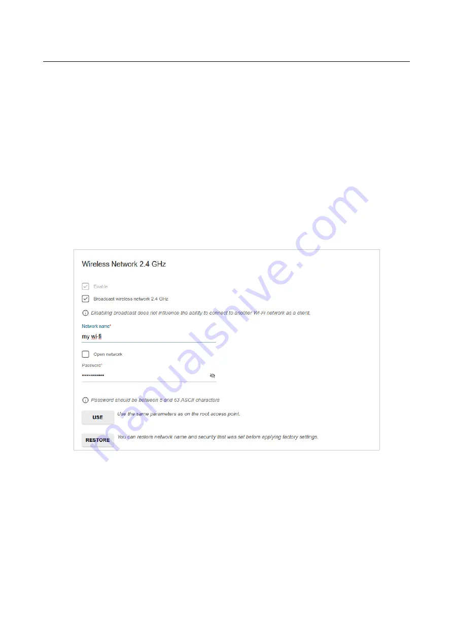
1. On the
Wireless Network 2.4 GHz
page, in the
Network name
field, specify your own
name for the wireless network in the 2.4GHz band or leave the value suggested by the
router.
2. In the
Password
field, specify your own password for access to the wireless network or
leave the value suggested by the router (WPS PIN of the device, see the barcode label).
3. If the router is used as a Wi-Fi client, you can specify the same parameters of the wireless
network as specified for the network to which you are connecting. To do this, click the
USE
button (available for the
WISP Repeater
and
Repeater
modes only).
4. You can restore the parameters of the wireless network specified before resetting to factory
defaults. To do this, click the
RESTORE
button.
Figure 52. The page for configuring the wireless network.
Page
69
of 358


