background image


Information in this document is subject to change without notice. 

© 2007 D-Link Computer Corporation. All rights reserved. 

Reproduction in any manner whatsoever without the written permission of D-Link Computer Corporation is strictly 
forbidden. 

Trademarks used in this text: D-Link and the D-Link logo are trademarks of D-Link Computer Corporation; Microsoft and 
Windows are registered trademarks of Microsoft Corporation. 

Other trademarks and trade names may be used in this document to refer to either the entities claiming the marks and names 
or their products. D-Link Computer Corporation disclaims any proprietary interest in trademarks and trade names other than 
its own. 

FCC Warning 

This equipment has been tested and found to comply with the limits for a Class A digital device, pursuant to Part 15 of the 
FCC Rules. These limits are designed to provide reasonable protection against harmful interference when the equipment is 
operated in a commercial environment. This equipment generates, uses, and can radiate radio frequency energy and, if not 
installed and used in accordance with this user’s guide, may cause harmful interference to radio communications. Operation 
of this equipment in a residential area is likely to cause harmful interference in which case the user will be required to 
correct the interference at his own expense. 

CE Mark Warning 

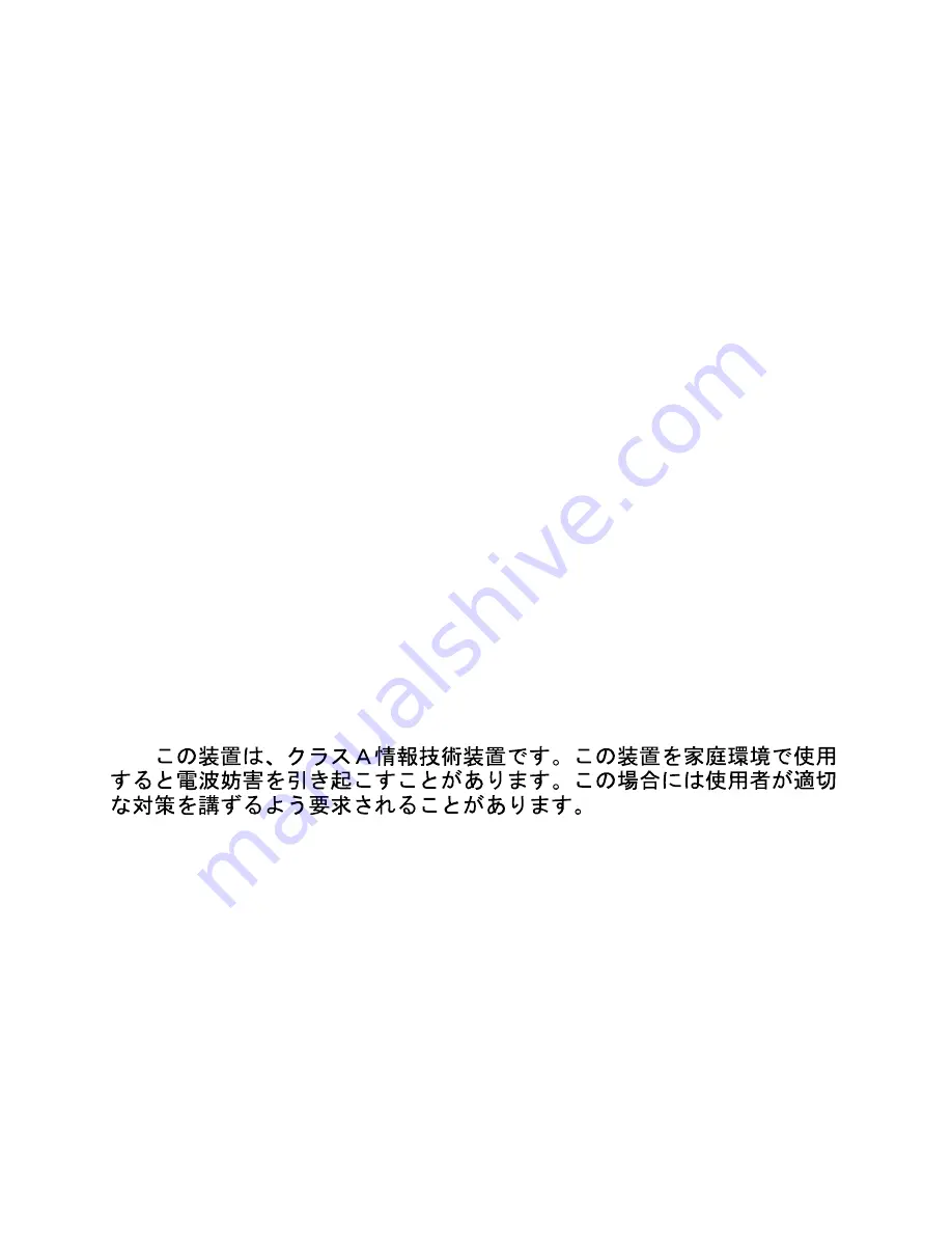
This is a Class A product. In a domestic environment, this product may cause radio interference in which case the user may 
be required to take adequate measures. 

Warnung! 

Dies ist ein Produkt der Klasse A. Im Wohnbereich kann dieses Produkt Funkstoerungen verursachen. In diesem Fall kann 
vom Benutzer verlangt werden, angemessene Massnahmen zu ergreifen. 

Precaución! 

Este es un producto de Clase A. En un entorno doméstico, puede causar interferencias de radio, en cuyo case, puede 
requerirse al usuario para que adopte las medidas adecuadas. 

Attention! 

Ceci est un produit de classe A. Dans un environnement domestique, ce produit pourrait causer des interférences radio, 
auquel cas l`utilisateur devrait prendre les mesures adéquates. 

Attenzione! 

Il presente prodotto appartiene alla classe A. Se utilizzato in ambiente domestico il prodotto può causare interferenze radio, 
nel cui caso è possibile che l`utente debba assumere provvedimenti adeguati. 


VCCI Warning 


December 2007 P/N  


Summary of Contents for DES-1228 - Web Smart Switch

Page 1: ...Version 2 00 ...

Page 2: ...d used in accordance with this user s guide may cause harmful interference to radio communications Operation of this equipment in a residential area is likely to cause harmful interference in which case the user will be required to correct the interference at his own expense CE Mark Warning This is a Class A product In a domestic environment this product may cause radio interference in which case ...

Page 3: ...4 Supported Web Browsers 4 Connecting to the Switch 4 Login Web based Management Utility 5 Smart Wizard 5 Web based Management Utility 5 SmartConsole Utility 5 Product Introduction 7 DES 1228 7 Front Panel 8 Rear Panel 8 DES 1228P 8 Front Panel 8 Rear Panel 9 DES 1252 9 Front Panel 9 Rear Panel 10 SmartConsole Utility 11 SmartConsole Settings 11 Utility Settings 11 Log 12 Trap 12 File 12 Help 13 D...

Page 4: ...DES 1228P 34 Power over Ethernet PoE PoE System Settings Only for DES 1228P 35 QoS 802 1p DSCP Priority Settings 35 Security Trusted Host 37 Security Safeguard Engine 37 Security Broadcast Storm Control 37 Security 802 1X Settings 39 Security Mac Address Table Static Mac 40 Security Mac Address Table Dynamic Forwarding Table 40 Monitoring Statistics 41 Monitoring Cable Diagnostics 42 Appendix A Et...

Page 5: ...have to insert http in front of the web address For the latest information of D Link Web Smart Switches and the professional technical Resource Website D Link www dlink com tw Technical Support tsd dlink com tw Terms Usage In this guide the term Switch first letter capitalized refers to the Smart Switch and switch first letter lower case refers to other Ethernet switches Some technologies refer to...

Page 6: ...tion and operation it is recommended that you Visually inspect the power cord to see that it is secured fully to the AC power connector Make sure that there is proper heat dissipation and adequate ventilation around the switch Do not place heavy objects on the switch Desktop or Shelf Installation When installing the switch on a desktop or shelf the rubber feet included with the device must be atta...

Page 7: ...rack or chassis Step 3 Plugging in the AC Power Cord Users may now connect the AC power cord into the rear of the switch and to an electrical outlet preferably one that is grounded and surge protected Figure 4 Plugging the switch into an outlet Power Failure As a precaution the switch should be unplugged in case of power failure When power is resumed plug the switch back in 3 3 ...

Page 8: ...ility you don t need to change the IP address of your PC and it is easy to start the initial setting of multiple Smart Switches Please refer to the following detailed installation instructions for the Web Based Management Utility and the SmartConsole Utility Using Web based Management Utility After a successful physical installation you can configure the Switch monitor the LED panel and display st...

Page 9: ... automatically load the web configuration in your web browser When the following login box appears enter the password then press OK to entering the Web based Management Utility The default password is Admin Figure 7 Log in screen Smart Wizard Before entering the Web based Management Utility When The Smart Wizard will guide you to quick configure the D Link Web Smart Switch Please refer to Samrt Wi...

Page 10: ... of your PC and use the SmartConsole Utility to discover the Smart Switches Option 2 Follow these steps to install the SmartConsole Utility manually 1 Insert the Utility CD into your CD Rom Drive 2 From the Start menu on the Windows desktop choose Run 3 In the Run dialog box type D D Link SmartConsole Utility setup exe where D represents the drive letter of your CD Rom and click OK 4 Follow the on...

Page 11: ...ling users to run bandwidth sensitive applications such as streaming multimedia and VoIP in network These functions allow switches to work seamlessly with VLAN and 802 1p traffic in network Asymmetric VLAN is implemented in these switches for a more efficient use of shared resources such as server or gateway devices Network Security D Link s innovative Safeguard Engine function protects the switch...

Page 12: ...Reset By pressing the Reset button the Switch will change back to the default configuration and all changes will be lost Rear Panel Figure 9 DES 1228 Rear Panel Power The power port is where to connect the AC power cord DES 1228P 24 Port 10 100Mpbs PoE Smart Switch with 4 Port 10 100 1000Mbps and 2 Combo SFPs Front Panel Figure 10 DES 1228P Front Panel Power LED The Power LED lights up when the Sw...

Page 13: ...ar Panel Power The power port is where to connect the AC power cord DES 1252 48 Port 10 100Mpbs Smart Switch with 4 Port 10 100 1000Mbps and 2 Combo SFPs Front Panel Figure 12 DES 1252 Front Panel Power LED The Power LED lights up when the Switch is connected to a power source CPU LED When the CPU LED is blinking then the switch is in the normal condition If the CPU LED is off or stays in solid li...

Page 14: ...3 Product Introduction D Link Web Smart Switch User Manual Rear Panel Figure 13 DES 1252 Rear Panel Power The power port is where to connect the AC power cord 1 10 0 ...

Page 15: ...artConsole Settings The SmartConsole Settings at the left has five icons Utility Settings Log Trap File and Help Utility Settings By clicking on this icon the Utility Settings window will pop up Refresh time refreshes the devices which were selected as monitored device in the Device List Choices include 15 secs 30 secs 1mins 2mins and 5 mins for selecting the monitoring time intervals Utility Grou...

Page 16: ...e Log Trap By clicking on this icon the Trap window will pop up Click View Trap to show the events of the SmartConsole Utility and the device Date Time indicates when the trap was received IP indicates where it comes from and Status shows the content of this trap message Click Clear Trap to clear all entries Click OK to exit Figure 17 SmartConsole Trap The trap icon in the SmartConsole Settings wi...

Page 17: ... as default for the next time the SmartConsole Utility is used Monitor Save As To record the setting of the Device List in an appointed filename and file path Monitor Load To manually load a Device List setting file Help By clicking on this icon a window with information about the SmartConsole will pop up Figure 19 SmartConsole Help 1 13 3 ...

Page 18: ...ce buttons for the Device List Device Settings Select a switch from the Device List then clicking on this icon the Device Settings window will pop up Here you can configure the Product Name IP Address Gateway Subnet Mask System Name Location Trap IP Switch Group Interval and DHCP Setting of the Switch To apply the configuration insert the correct device password in Confirm Password then click OK F...

Page 19: ...hen input the correct password of device and click Upgrade and wait the upgrade successfully message pop up to complete the firmware upgrade Figure 22 Firmware Upgrade CAUTION Do not disconnect the PC or remove the power cord from device until upgrade complete Switch may crash if Firmware upgrade incompletely DHCP Refresh If the DHCP enabled switch in Device List shows the default IP which means t...

Page 20: ...ent PC are listed in the Device List Click the and insert the device IP address to add a device into Discover List or select a device and click the button to remove it Figure 24 SmartConsole Add device Figure 25 SmartConsole Delete device Device List This is the list where all Web Smart devices on the network are discovered Figure 26 SmartConsole Device List Definitions of the Device List features...

Page 21: ...ame Shows the device product name System Name Shows the appointed device system name DHCP Specify if the IP address of this device is from DHCP server or manual configured Location Shows where the appointed device location Trap IP Shows the IP where the Trap information will be sent Subnet Mask Shows the Subnet Mask setting of the device Gateway Shows the Gateway setting of the device Device Group...

Page 22: ...nt Utility When The Smart Wizard will guide you to quick configure some functions If you don t plan to change anything click Exit to exit the Wizard and enter the Web Interface Password Settings Password setting allows you to change the login password of the device Type the desired new password in the Switch Password box and again in the Confirm Switch Password then click the Apply button to chang...

Page 23: ...nction description please see Setup Menu System SNMP Settings The default SNMP Setting is Disabled Click Enabled the Apply to configure Community Settings Public Read only privilege allows authorized management stations to retrieve MIB objects Private Read write privilege allows authorized management stations to retrieve and modify MIB objects Figure 28 Configure SNMP in Smart Wizard 1 19 9 ...

Page 24: ...ure System IP address in Smart Wizard NOTE Changing the system IP address will disconnect you from your internet connection please enter the correct IP address in the Web browser and make sure your PC is in the same subnet with the switch See Login Web based Management Utility for detail description If you want to change the IP settings click YES and start a new web browser Figure 30 Confirm the c...

Page 25: ...sing different functions in the function tree you can change all the configurations in the Main Configuration Screen The main configuration screen will show the current status of your Switch by clicking the model name on top of the function tree At the upper right of the screen you can see your username and current IP address Under your username is the Logout button Click this to end this session ...

Page 26: ...ore Click Backup to save the current settings to your disk Click Browse to browse your inventories for a saved backup settings file Click Restore after selecting the backup settings file you want to restore Note To restore the configuration the switch will restart and all current configurations will be lost Firmware Backup and Upload Allow for the firmware to be saved or for an existing firmware f...

Page 27: ...P mode the Switch will first look for a DHCP server to provide it with an IP address network mask and default gateway before using the default or previously entered settings By default the IP setting is static mode System Information By entering a System Name and System Location the device can more easily be recognized through the SmartConsole Utility and in other Web Smart devices on the LAN Logi...

Page 28: ...nation IP address of the managing station that will receive trap information Figure 39 System Trap Setting You can choose which event to send to the managing station System Event Monitors the system s trapping information Device Bootup Traps system boot up information Illegal Login Traps events of incorrect password logins recording the IP of the originating PC Fiber Port Link Up Link Down Traps f...

Page 29: ... settings in Qos 802 1p Default Priority NOTE When the Combo Fiber port and the Copper ports are both connected the Fiber port will take precedence over the Copper ports meaning the Fiber port will be the only connection System SNMP Settings Simple Network Management Protocol SNMP is an OSI Layer 7 Application Layer designed specifically for managing and monitoring network devices SNMP enables net...

Page 30: ...us as a reboot someone accidentally turned the Switch OFF or less serious events such as a port status change The Switch can generate traps and send them to the trap recipient i e network administrator Setting up a Trap Select Enable enter a Trap Name add the IP of the device to be monitored and choose the event s to trap The available trap Events to choose from including System Device Bootup Fibe...

Page 31: ...ces to a new VLAN without having to change any physical connections The IEEE 802 1Q VLAN Configuration page provides powerful VID management functions The original settings have the VID as 01 named default and all ports as Untagged Rename Click to rename the VLAN group Delete VID Click to delete the VLAN group Add New VID Click to create a new VID group assigning ports from 01 to 28 as Untag Tag o...

Page 32: ...the 802 1Q Configuration page it allows devices in different VLANs to communicate with the servers firewalls or other shared resource in the shared VLAN This configuration is accomplished in three steps 1 Enabling Asymmetric VLAN 2 Creating VLAN 3 Setting PVID Figure 47 Configuration 802 1Q VLAN Asymmetric VLAN Click Example to open the page and follow the instructions below to configure Asymmetri...

Page 33: ...three VLANs that share ports and are separated from each other so cannot communicate with each other 3 Configure the PVID setting located in the bottom of VLAN configuration page The user needs to set the shared set of ports as PVID 1 the other separated groups of ports as PVID 2 3 and 4 Figure 49 Configuration 802 1Q VLAN Configure PVID After configuration the user is able to share the network re...

Page 34: ...ined trunk port must be connected to devices within the same VLAN group Configuration IGMP Snooping With Internet Group Management Protocol IGMP snooping the Web Smart Switch can make intelligent multicast forwarding decisions by examining the contents of each frame s Layer 2 MAC header IGMP snooping can help reduce cluttered traffic on the LAN With IGMP snooping enabled globally the Web Smart Swi...

Page 35: ...esults in reduced time to detect the loss of the last member of a group Default is 1 second Host Timeout System assigned This is the interval after which a learnt host port entry will be purged For each host port learnt a Port Purge Timer runs for Host Port Purge Interval This timer will be restarted whenever a report message from host is received over that port If no report messages are received ...

Page 36: ...ed to prevent network loops that could cause a broadcast storm When physical links forming a loop provide redundancy only a single path will be forwarding frames If the link fails STP activates a redundant link automatically Figure 55 Configuration Spanning Tree By default Spanning Tree is disabled If enabled the Switch will listen for BPDU packets and its accompanying Hello packet BPDU packets ar...

Page 37: ...mum amount of time that the root device will wait before changing states The default is 15 seconds Root Bridge Displays the MAC address of the Root Bridge Root port Displays the root port Root Path Cost Shows the root path cost In addition to 802 1D global settings the D Link Web smart switch allows the user to configure 802 1D STP by ports Select From Port To Port to specify the ports you want to...

Page 38: ...discover the DWL 3140AP and user may central manage the all the DWL 3140AP by the optional D Link Smart WLAN Manager Figure 57 Configuration LLDP Power over Ethernet PoE PoE Port Settings Only for DES 1228P DES 1228P supports Power over Ethernet PoE as defined by the IEEE 802 3af specification Ports 1 24 can supply 50VDC power to PDs Powered Device over Category 5 or Category 3 UTP Ethernet cables...

Page 39: ...28P This page will display the PoE status including System Budget Power Support Total Power Remainder Power and The ratio of system power supply Figure 59 PoE PoE System Setting System Power Threshold When the ratio of the system power supply is larger than or smaller than the System Power Threshold Setting the Switch will send trap events to the Management Station Note When there is a system powe...

Page 40: ...nding on your configuration Figure 60 QoS 802 1p Default Priority By selecting the DSCP priority the web pages will changes as seen below Figure 61 QoS DSCP Priority Settings Select QoS Mode D Link Smart Switch allows the user to prioritize the traffic based on the 802 1p priority in the VLAN tag or the DSCP Differentiated Services Code Point priority in the IP header Choose one to prioritize the ...

Page 41: ... setting the format can be either 192 168 1 1 255 255 255 0 or 192 168 0 1 24 Please see below for the example for permitting the IP range IP Address IP Mask Permitted IP 192 168 0 1 255 255 255 0 192 168 0 1 192 168 0 255 172 17 5 215 8 172 0 0 1 172 255 255 255 To delete the IP address simply click the Delete Host button check the unwanted address then click Apply Security Safeguard Engine D Lin...

Page 42: ...5 Configuration D Link Web Smart Switch User Manual Figure 64 Security Broadcast Storm Control 3 38 8 ...

Page 43: ...ty select enabled and set the 802 1X Global Settings for the Radius Server and applicable authentication information Authentication Port sets primary port for security monitoring Default is 1812 Key Masked password matching the Radius Server Key Confirm Key Enter the Key a second time for confirmation TxPeriod Sets the number of seconds that the switch waits for a response to an EAP request identi...

Page 44: ...ing for any of the uplink ports press On to enable this feature and select the port s for auto learning to be disabled The Static Mac Address Setting table displays the static Mac addresses connected as well as the VID Press Delete to remove a device To add a new Mac address assignment press Add Mac then select the assigned Port number enter both the Mac Address and VID and press Apply Security Ma...

Page 45: ...llected and displayed Clear Counter To reset the details displayed TxOK Number of packets transmitted successfully RxOK Number of packets received successfully TxError Number of transmitted packets resulting in error RxError Number of received packets resulting in error To view the statistics of individual ports click one of the linked port numbers for details Figure 69 Monitoring Port Statistics ...

Page 46: ...Open in Cable means the lines of RJ45 cable maybe broken or the other end of the cable is simply disconnected Test Failed means some other errors occurred during cable diagnostics Please select the same port and test again Cable Fault Distance meters Indicates the distance of the cable fault from the Switch port if the cable is less than 2 meters it will show No Cable Cable Length meter If the tes...

Page 47: ...ackbone server connection which will create a flexible foundation for the next generation of network technology products Fast Ethernet Technology The growing importance of LANs and the increasing complexity of desktop computing applications are fueling the need for high performance networks A number of high speed LAN technologies have been proposed to provide greater bandwidth and improve client s...

Page 48: ...orting category 5 5e up to 100 Meters PoE will provide power to PoE compatible devices such as IP telephones wireless LAN access points and IP security cameras PoE is already widely adopted in the market saving up to 50 of overall installation costs by eliminating the need to install separate electrical wiring and power outlets ...

Page 49: ...330R TX 1310 RX 1550nm DEM 331T TX 1550 RX 1310nm DEM 331R TX 1310 RX 1550nm Power over Ethernet DES 1228P Only PoE Capable Ports Port 1 24 Supplies power up to 15 4W per port compliant with IEEE802 3af standards Power Budget 170W max Auto discovery Auto disable port if the port current is over 350mA Following the standard classification 0 15 4W 1 4 0W 2 7 0W 3 15 4W 4 15 4W Physical Environment A...

Page 50: ...itch User Manual Trap setting for destination IP system events fiber port events twisted pair port events Port access control Web based configuration backup restoration Web based firmware backup upload Firmware upgrade using SmartConsole Utility Reboot 2 2 ...

Page 51: ... customers can contact D Link technical support through our website or by phone Tech Support for customers within the United States D Link Technical Support over the Telephone 877 354 6555 Monday to Friday 8 00am to 5 00pm PST D Link Technical Support over the Internet http support dlink com email support dlink com Tech Support for customers within Canada D Link Technical Support over the Telephon...

Page 52: ...n The United Kingdom Ireland D Link UK Ireland Technical Support over the Internet http www dlink co uk ftp ftp dlink co uk D Link UK Ireland Technical Support over the Telephone 08456 12 0003 United Kingdom 1890 886 899 Ireland Lines Open 9 00 am 06 00 pm Mon Fri 10 00am 02 00 pm Sat Closed on Sun For Customers within Canada D Link Canada Technical Support over the Telephone 1 800 361 5265 Canada...

Page 53: ...g über unsere Website per E Mail oder telefonisch anfordern Web http www dlink de E Mail support dlink de Telefon 49 1805 2787 0 12 Min aus dem Festnetz der Deutschen Telekom Telefonische technische Unterstützung erhalten Sie Montags bis Freitags von 09 00 bis 17 30 Uhr Unterstützung erhalten Sie auch bei der Premiumhotline für D Link Produkte unter der Rufnummer 09001 475767 Montag bis Freitag vo...

Page 54: ...Assistance technique D Link par téléphone 0820 0803 03 N INDIGO 0 12 TTC min Prix en France Métropolitaine au 3 mars 2005 Du lundi au samedi de 9h00 à 19h00 Assistance technique D Link sur internet http www dlink fr e mail support dlink fr Support technique destiné aux clients établis au Canada Assistance technique D Link par téléphone 800 361 5265 Lun Ven 7h30 à 21h00 HNE Assistance technique D L...

Page 55: ... Link ofrece asistencia técnica gratuita para clientes residentes en España durante el periodo de garantía del producto Asistencia Técnica de D Link por teléfono 34 902 30 45 45 Lunes a Viernes de 9 00 a 14 00 y de 15 00 a 18 00 Asistencia Técnica de D Link a través de Internet http www dlink es support e mail soporte dlink es ...

Page 56: ...sito D Link Supporto tecnico per i clienti residenti in Italia D Link Mediterraneo S r L Via N Bonnet 6 B 20154 Milano Supporto Tecnico dal lunedì al venerdì dalle ore 9 00 alle ore 19 00 con orario continuato Telefono 199 400057 URL http www dlink it supporto html Email tech dlink it ...

Page 57: ...herlands D Link Technical Support over the Telephone 0900 501 2007 Monday to Friday 9 00 am to 10 00 pm D Link Technical Support over the Internet www dlink nl Tech Support for customers within Belgium D Link Technical Support over the Telephone 070 66 06 40 Monday to Friday 9 00 am to 10 00 pm D Link Technical Support over the Internet www dlink be Tech Support for customers within Luxemburg D Li...

Page 58: ...nia bezpłatną pomoc techniczną klientom w Polsce w okresie gwarancyjnym produktu Klienci z Polski mogą się kontaktować z działem pomocy technicznej firmy D Link za pośrednictwem Internetu lub telefonicznie Telefoniczna pomoc techniczna firmy D Link 0 801 022 021 Pomoc techniczna firmy D Link świadczona przez Internet URL http www dlink pl ...

Page 59: ...my D Link D Link poskytuje svým zákazníkům bezplatnou technickou podporu Zákazníci mohou kontaktovat oddělení technické podpory přes webové stránky mailem nebo telefonicky Web http www dlink cz suppport E mail support dlink cz Telefon 224 247 503 Telefonická podpora je v provozu PO PÁ od 09 00 do 17 00 ...

Page 60: ...t munkanapokon hétfőtől csütörtökig 9 00 16 00 óráig és pénteken 9 00 14 00 óráig kérhet a 1 461 3001 telefonszámon vagy a support dlink hu emailcímen Magyarországi technikai támogatás D Link Magyarország 1074 Budapest Alsóerdősor u 6 R70 Irodaház 1 em Tel 06 1 461 3001 Fax 06 1 461 3004 email support dlink hu URL http www dlink hu ...

Page 61: ...sider D Link tilbyr sine kunder gratis teknisk support under produktets garantitid Kunder kan kontakte D Links teknisk support via våre hjemmesider eller på tlf Teknisk Support D Link Teknisk telefon Support 800 10 610 Hverdager 08 00 20 00 D Link Teknisk Support over Internett http www dlink no ...

Page 62: ...byder gratis teknisk support til kunder i Danmark i hele produktets garantiperiode Danske kunder kan kontakte D Link s tekniske support via vores hjemmeside eller telefonisk D Link teknisk support over telefonen Tlf 7026 9040 Hverdager kl 08 00 20 00 D Link teknisk support på Internettet http www dlink dk ...

Page 63: ...a teknistä tukea asiakkailleen Tuotteen takuun voimassaoloajan Tekninen tuki palvelee seuraavasti Arkisin klo 9 21 numerosta 0800 114 677 Internetin kautta Ajurit ja lisätietoja tuotteista http www dlink fi Sähköpostin kautta voit myös tehdä kyselyitä ...

Page 64: ... annan användarinformation D Link tillhandahåller teknisk support till kunder i Sverige under hela garantitiden för denna produkt Teknisk Support för kunder i Sverige D Link Teknisk Support via telefon 0770 33 00 35 Vardagar 08 00 20 00 D Link Teknisk Support via Internet http www dlink se ...

Page 65: ... site de D Link Portugal http www dlink pt A D Link fornece suporte técnico gratuito para clientes no Portugal durante o período de vigência de garantia deste produto Suporte Técnico para clientes no Portugal Assistência Técnica Email soporte dlink es http www dlink pt support ftp ftp dlink es ...

Page 66: ...δωρεάν υποστήριξη στον Ελλαδικό χώρο Μπορείτε να επικοινωνείτε με το τμήμα τεχνικής υποστήριξης μέσω της ιστοσελίδας ή μέσω τηλεφώνου Για πελάτες εντός του Ελλαδικού χώρου Τηλεφωνική υποστήριξη D Link Τηλ 210 86 11 114 Φαξ 210 86 53 172 Δευτέρα Παρασκευή 09 00 17 00 e mail support dlink gr Τεχνική υποστήριξη D Link μέσω Internet http www dlink gr ftp ftp dlink it ...

Page 67: ...p www dlink co in support productsupport aspx Indonesia Malaysia Singapore and Thailand Tel 62 21 5731610 Indonesia Tel 1800 882 880 Malaysia Tel 65 66229355 Singapore Tel 66 2 719 8978 9 Thailand Monday to Friday 9 00am to 6 00pm http www dlink com sg support e mail support dlink com sg Korea Tel 82 2 890 5496 Monday to Friday 9 00am to 6 00pm http www d link co kr e mail lee d link co kr New Zea...

Page 68: ...l support e mail support dlink co il Pakistan Tel 92 21 4548158 or 92 21 4548310 Sunday to Thursday 9 00am to 6 00pm http support dlink me com e mail support pk dlink me com South Africa and Sub Sahara Region Tel 27 12 665 2165 08600 DLINK for South Africa only Monday to Friday 8 30am to 9 00pm South Africa Time http www d link co za Turkey Tel 90 212 2895659 Monday to Friday 9 00am to 6 00pm http...

Page 69: ...Link D Link предоставляет бесплатную поддержку для клиентов в течение гарантийного срока Клиенты могут обратиться в группу технической поддержки D Link по телефону или через Интернет Техническая поддержка D Link 495 744 00 99 Техническая поддержка через Интернет http www dlink ru e mail support dlink ru ...

Page 70: ...Viernes 08 00 am a 21 00 pm Soporte Técnico Help Desk Colombia Teléfono 01800 9525465 Lunes a Viernes 07 00 am a 20 00 pm Soporte Técnico Help Desk Ecuador Teléfono 1800 035465 Lunes a Viernes 07 00 am a 20 00 pm Soporte Técnico Help Desk El Salvador Teléfono 800 6335 Lunes a Viernes 06 00 am a 19 00 pm Soporte Técnico Help Desk Guatemala Teléfono 1800 8350255 Lunes a Viernes 06 00 am a 19 00 pm S...

Page 71: ...brasil com br A D Link fornece suporte técnico gratuito para clientes no Brasil durante o período de vigência da garantia deste produto Suporte Técnico para clientes no Brasil Telefone São Paulo 11 2185 9301 Segunda à sexta Das 8h30 às 18h30 Demais Regiões do Brasil 0800 70 24 104 E mail e mail suporte dlinkbrasil com br ...

Page 72: ...方式與D Link台灣 地區技術支援工程師聯絡 D Link 免付費技術諮詢專線 0800 002 615 服務時間 週一至週五 早上8 30到晚上9 00 不含周六 日及國定假日 網 站 http www dlink com tw 電子郵件 dssqa_service dlink com tw 如果您是台灣地區以外的用戶 請參考D Link網站全球各地 分公司的聯絡資訊以取得相關支援服務 產品保固期限 台灣區維修據點查詢 請參考以下網頁說明 http www dlink com tw 產品維修 使用者可直接送至全省聯強直營維修站或請洽您的原購買經銷商 ...

Page 73: ...okumentasi pengguna dapat diperoleh pada situs web D Link Dukungan Teknis untuk pelanggan Dukungan Teknis D Link melalui telepon Tel 62 21 5731610 Dukungan Teknis D Link melalui Internet Email support dlink co id Website http support dlink co id ...

Page 74: ...用手冊 办公地址 北京市东城区北三环东路 36 号 环球贸易中心 B 座 26F 02 05 室 邮编 100013 技术支持中心电话 8008296688 028 66052968 技术支持中心传真 028 85176948 维修中心地址 北京市东城区北三环东路 36 号 环球贸易中心 B 座 26F 02 05 室 邮编 100013 维修中心电话 010 58257789 维修中心传真 010 58257790 网址 http www dlink com cn ...

Page 75: ...L www dlink eu Spain Avenida Diagonal 593 95 9th floor 08014 Barcelona Spain TEL 34 93 409 07 70 FAX 34 93 491 07 95 URL www dlink es Sweden Gustavslundsvägen 151B S 167 51 Bromma Sweden TEL 46 0 8 564 619 00 FAX 46 0 8 564 619 01 URL www dlink se Switzerland Glatt Tower 2 OG Postfach CH 8301 Glattzentrum Switzerland TEL 41 0 1 832 11 00 FAX 41 0 1 832 11 01 URL www dlink ch Singapore 1 Internatio...

Page 76: ......

Reviews: