background image

64

D-Link DCS-6314 User Manual

Section 3: Configuration

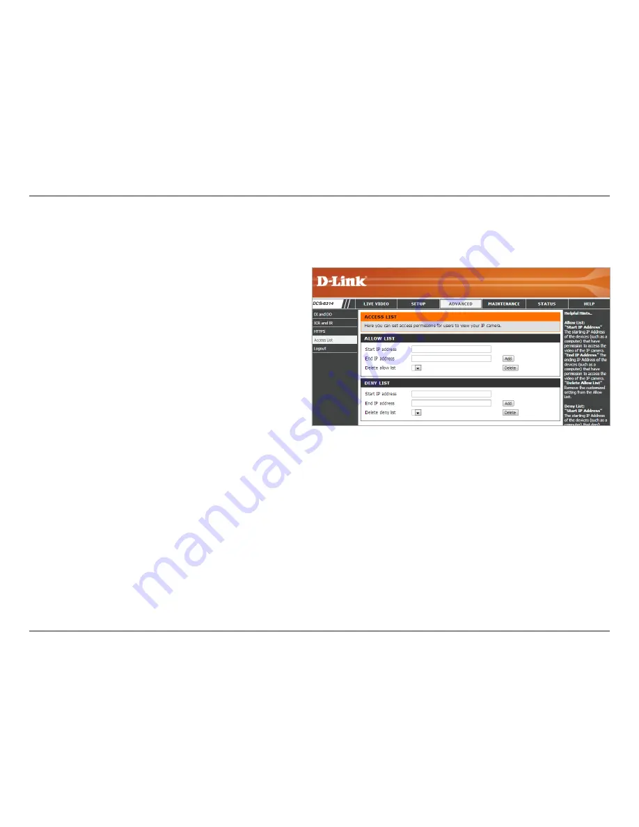
Access List

Here you can set access permissions for users to view your DCS-6314. 

Allow List /Start 

IP address:

End IP address:

Delete allow list:

Deny List /Start 

IP Address:

End IP address:

Delete deny list:

The starting 

IP Address

 of the device(s), such as a 

computer, that have permission to access the 

video from the camera. Click 

Add

 to save.

Note:


A total of seven IP addresses can be configured 

for each section

.

The ending 

IP Address

 of the device(s), such as a 

computer, that have permission to access the 

video from the camera. Click 

Add

 to save.

Remove the 

IP Adddresses

 from the 

Allow List

.

The starting 

IP Address

 of device(s), such as a 

computer, that 

do not

 have access rights to the 

video from the camera. Click 

Add 

to save.

The ending 

IP Address

 of the device(s), such as a 

computer, that 

do not

 have permission to access 

the video from the camera. Click 

Add

 to save.

Remove the 

IP Addresses

 from the 

Delete

 List.

For example:

When the range of the Allowed List is set from 

1.1.1.0 to 192.255.255.255 and the range of the 

Denied List is set from 1.1.1.0 to 170.255.255.255. 

Only users with IPs located between 171.0.0.0 and 

192.255.255.255 can access the Network Camera.

Summary of Contents for DCS-6314

Page 1: ...User Manual Version 1 0 06 27 2013 DCS 6314 Full HD Outdoor Fixed Dome Network Camera ...

Page 2: ... 27 2013 Initial Release for Revision A1 with firmware version 1 00 Trademarks D Link and the D Link logo are trademarks or registered trademarks of D Link Corporation or its subsidiaries in the United States or other countries All other company or product names mentioned herein are trademarks or registered trademarks of their respective companies Copyright 2013 D Link Corporation All rights reser...

Page 3: ...d 24 General Connection Using 12 V DC Power Adapter 24 Connection Using Power over Ethernet 25 Software Installation 26 D ViewCam Setup Wizard 29 Configuration 31 Using the Configuration Interface 31 Live Video 32 Setup 34 Setup Wizard 34 Internet Connection Setup Wizard 35 Motion Detection Setup Wizard 38 Network Setup 40 Dynamic DNS 43 Image Setup 44 Audio and Video 46 Preset 48 Motion Detection...

Page 4: ...4 D Link DCS 6314 User Manual Status 68 Device Info 68 Logs 69 Help 70 DI DO Specifications 71 Technical Specifications 72 Contacting Technical Support 75 Warranty 76 Registration 82 ...

Page 5: ...with User Manual and software Quick Installation Guide Security Wrench CAT5 Ethernet cable Weather Shield Screws and wall socket 4 Pin Terminal Block If any of the above items are missing please contact your reseller Note Using a power supply with a different voltage than the one included with your product will cause damage and void the warranty for this product ...

Page 6: ...t in removable IR cut filter and IR LEDs give the DCS 6314 the capability to view up to 49 feet at night The camera supports PoE Power over Ethernet allowing it to be easily installed in a variety of locations without the need for supplemental power cabling This combination of features makes the DCS 6314 a high performance reliable cost effective 24 hour surveillance solution Installation is simpl...

Page 7: ...ia Intranet or Internet Other features include image monitoring recording images to a hard drive viewing up to 32 cameras on one screen and taking snapshots IR LED for Day and Night Functionality The built in infrared LEDs enable nighttime viewing of up to 49 feet 15 meters IP68 Weatherproof Housing TheDCS 6314usesanIP68weatherproofhousing Soyoucanrestassuredthatevenunderthetoughestconditions this...

Page 8: ... sensor measures the lighting conditions and switches between color and infrared accordingly 2 Camera Lens Vari focal lens records video of the surrounding area 3 IR LEDs Infrared LEDs illuminate the camera s field of view at night 4 Power Status LED Status LED indicates the camera s current status 3 4 2 1 ...

Page 9: ...ed to attach to the optional mounting accessories 1 2 3 Note With the weathershield attached the video may show reflections when the IR LEDs are on and the camera is at a high angle If you experience this lower the angle of the camera or turn off the IR LEDs For details on how to adjust the camera angle refer to Orienting the Camera on page 23 For details on how to turn the IR LEDs on off see ICR ...

Page 10: ...io Out Green Connects to a speaker 3 Audio In Red Connects to a microphone 4 Power Connector Power connector for the provided 12V DC power adapter 5 Ethernet Jack Connects to an RJ 45 Ethernet port Can be used with PoE to provide power to the camera 6 Reset Button Press and hold the recessed button for 10 seconds to reset the camera 1 4 5 6 3 2 ...

Page 11: ...ction 1 Product Overview Internal 1 microSD Card Slot Insert a microSD card for storing recorded images and video Note For step by step instructions on how to insert a microSD card refer to Installing a microSD Card on the next page 1 ...

Page 12: ...ing a microSD Card Step 1 Place the camera face down on a non slip flat surface Step 3 Remove the base of the camera by holding the camera firmly and rotating the base in a counter clockwise direction Step 2 Remove the adjustable top part of the camera housing after removing the three retaining screws ...

Page 13: ...ase of the camera by holding the camera firmly and rotating the base in a clockwise direction ensuring a tight fit Note Make sure the weatherproof seals are secured firmly in place Step 4 Insert your microSD memory card into the slot with the notch oriented toward the front of the camera ...

Page 14: ...ions on page 74 for reference Step 2 Use a 6mm drill bit to make required holes approximately 30mm deep Step 3 Remove the Alignment Sticker Step 4 Insert wall anchors and attach the mounting plate using the screws provided Deploying the Camera Note Before deploying the camera to a fixed location it is recommended that you take a photo from the intended location to make sure the camera will have an...

Page 15: ...6314 User Manual Section 2 Assembly and Installation Step 5 Secure the camera to the mounting plate using the screw provided Make sure the cables are routed through the cable channel or via the mounting plate cut out ...

Page 16: ... removed use a screwdriver to remove the bottom mounting plate from the lower half of thecamerahousing Themountingplateissecuredwiththree screws positioned around the outer edge of the lower part of the camera housing Ifyouwillbemountingthecameradirectlytoawallorceiling continue to the next page Ifyouwillbemountingthecamerausingthependantmount refer to Attaching the Camera to the Pendant Mount on ...

Page 17: ...recommended that you leave the cable access panel attached as it will help protect the cable from vandalism If you will be installing the camera onto a surface that cannot house the cable the cable access part can be removed so that the cable can exit the camera housing easily Once the mounting plate is removed you will be able to remove the cable access panel Step 4 Slidethelowerhalfofthecameraho...

Page 18: ...he camera housing and secure it by tightening the three retaining screws Step 6 If needed the included weather shield can now be attached to the camera Note If you are installing the DCS 6314 in a location where it will be exposed to harsh weather it is recommended that you install the weather shield ...

Page 19: ...n in the diagram Step 2 Use the included mounting guide to mark the proper placement of the mounting holes on the ceiling Drill the corresponding holes Step 3 Place the rubber seal onto the mounting part of the pendant bracket Securely mount the rubber seal between the pendant bracket and the ceiling If you need more details see Deploying the Camera on page 14 Step 4 Attach the bracket cap by rota...

Page 20: ...nt Oncethecablehasbeenpushedthrough youcanthenfirmly reattach the bottom part of the camera housing Secure it by tightening the three retaining screws Step 6 Reattach the top part of the camera housing and secure it by tightening the three retaining screws Refer to Mounting the Camera on page 16 for more details including how to attach the weather shield to the camera Dome Camera ...

Page 21: ...o mark the proper placement of the mounting holes on the ceiling Drill the corresponding holes Step 3 Place the rubber seal onto the mounting part of the bent bracket Securely mount the rubber seal between the bent bracket and the ceiling If you need more details see Deploying the Camera on page 14 Step 4 Attach the bracket cap by rotating it counterclockwise in order to tighten it onto the bent b...

Page 22: ...nt mount Once the cable has been pushed through you can then firmly reattach the bottom part of the camera housing Secure it by tightening the three retaining screws Step 6 Reattach the top part of the camera housing and secure it by tightening the three retaining screws Refer to Mounting the Camera on page 16 for more details including how to attach the weather shield to the camera ...

Page 23: ...tep 2 Loosen the tilt screws on both sides of the camera and turn the lens module up and down until the desired position is achieved Tighten the tilt screws Step 3 Turn the lens to adjust the IP camera s image until the desired orientation is achieved The DCS 6314 can be adjusted to ensure an optimal viewing position when mounted to a wall by following the steps outlined ...

Page 24: ...sembly and Installation Camera Installation Wizard Step 1 Connect the network camera to a switch with an Ethernet cable Step 2 Connect the supplied power cable from the camera to a power outlet General Connection Using 12 V DC Power Adapter 2 1 ...

Page 25: ...on 2 Assembly and Installation Step 1 If you are using a PoE switch connect the IP camera to the switch with an Ethernet cable This will enable transmission of both power and data over a single cable Connection Using Power over Ethernet 1 ...

Page 26: ...Note If the autorun program does not automatically start on your computer go to Windows click Start Run In the Run command box type D autorun exe where D represents your CD ROM drive Step 2 Accept theEndUserLicenceAgreement Follow the on screen prompts to install the Camera Installation Wizard Step 3 Select your camera from the list then click Wizard If you have multiple cameras you can identify t...

Page 27: ...eate and confirm a password for your device Click Next to continue Step 5 Select Static IP if you want to manually enter the network settings supplied by your ISP Internet Service Provider Or select DHCP Dynamic IP if you want your router or DHCP servertoautomaticallyassignthecameraitsnetworksettings Note SelectDHCPifyouareunsureofwhichsettingstochoose Click Next to continue ...

Page 28: ...s and settings and then click Restart The LED on the front of the DCS 6314 will blink then turn solid green once it successfully connects to your network Step 7 Your DCS 6314 camera is now set up Click Exit to exit the wizard You can skip to Configuration on page 31 for advanced configuration of your camera ...

Page 29: ...to remotely manage multiple D Link IP cameras This software can be used to configure all the advanced settings for your cameras Step 1 Insert the CD ROM into the CD ROM drive Click Install D ViewCam Software from menu and select D ViewCam to install the VMS software Step 2 Follow the InstallShield Wizard to install D ViewCam Click Next to continue D ViewCam Setup Wizard ...

Page 30: ... Select Yes I want to restart my computer now or No I will restart my computer later Step 4 Remove any disks from drives and click Finish to complete the installation Step 5 For more details about using the D ViewCam software refer to the D ViewCam Manual on the included CD ...

Page 31: ...era The camera s built in Web configurationutilityisdesignedtoallowyoutoeasilyaccess and configure your DCS 6314 Step 1 Click the Link button on the wizard The Setup Wizard will automatically open your web browser to the IP address of your camera Step 2 Log in with the User Name admin and the Password you createdintheInstallationWizardtoaccesstheconfiguration interface Click OK 2 ...

Page 32: ...D card If no microSD card has been inserted this screen will display the message Card Invalid This field displays the status of your I O device if a device has been connected You may select a value for ePTZ electronically pan tilt and zoom between zero and 10 Zero is the slowest and 10 is the fastest This window indicates the total field of view FOV of the camera The red box indicates the visible ...

Page 33: ...FOV Stop Stops the camera ePTZ motion Preset Path Starts the camera s motion along the pre defined path Video Profile 1 Select s predefined settings configured on page 46 Video Profile 2 Select s alternate predefined settings configured on page 46 Full Screen Mode Will enlarge the video stream to use full screen Take a Snapshot Will record the current image Record Video Clip Will record a video cl...

Page 34: ...rnatively you may click Manual Internet Connection Setup to manually configure your Network Camera and skip to Network Setup on page 40 To configure your Network Camera s motion detection settings click Motion Detection Setup Wizard If you want to enter your settings manually click Manual Motion Detection Setup and skip to Motion Detection on page 50 ...

Page 35: ...ck Next to continue Select DHCP if your ISP Internet Service Provider has not provided you with connection settings or if you are not sure about your settings Select Static IP if you want to manually enter your connection settings or if you wish to set a static address within your home network Enter the settings into the required fields If you are using PPPoE check the box by Enable PPPoE and ente...

Page 36: ...3 Configuration If you have a Dynamic DNS account and would like the camera to update your IP address automatically select Enable DDNS and enter your host information Click Next to continue Enter an IP Camera Name and click Next to continue ...

Page 37: ...on Select the correct Time Zone to ensure that all events will be triggered as scheduled Click Next to continue Confirm the IP camera settings are correct and click Apply to save them The settings will be saved to the DCS 6314 and the camera will restart ...

Page 38: ...tton to specify whether the camera should capture a Snapshot or a Video Clip when motion is detected Refer to Motion Detection on page 50 for details about how to configure motion detection Step 2 This step allows you to enable motion detection based on a customized schedule Click on Always to make sure your camera always records whenever motion is detected Otherwise click on From and select the m...

Page 39: ...ify me if you choose not to receive notifications To receive notifications via Email or FTP click on the corresponding radio button Then enter the required information for your e mail or FTP account Click Next to continue Step 4 You have completed the Motion Detection Wizard Verify your settings and click Apply to save them Wait a few moments for the camera to save your settings and restart ...

Page 40: ... obtain a static or fixed IP address and other network information from your network administrator for your camera Enter the fixed IP address in this field This number is used to determine if the destination is inthesamesubnet Thedefaultvalueis255 255 255 0 The router gateway used to forward frames to destinations in a different subnet Invalid gateway settings may cause the failure of transmission...

Page 41: ...cryption Digest encryption uses MD5 hashes The port number that you use for RTSP streaming to mobile devices such as mobile phones or PDAs The default port number is 554 You may specify the address of a particular stream For instance live1 sdp can be accessed at rtsp x x x x video1 sdp where the x x x x represents the ip address of your camera Enabling the Class of Service setting implements a bes...

Page 42: ...ecify an Optional IP address specify an Optional default router and an Optional primary DNS The DCS 6314 allows you to multicast each of the available streams via Multicast group address and specify the TTL Time to Live value for each stream Check the box by Enable Multicast You can enter the port and TTL settings if you do not want to use the defaults Aftermakingyourselections clickonSaveSettings...

Page 43: ...e User Name Password Timeout Status Check this box to enable the DDNS function Enter the Server Address manually or select your Dynamic DNS provider from the drop down menu Enter the Host Name of the DDNS server Enter the User Name or e mail used to connect to your DDNS account Enter thePassword used to connect to your DDNS server account and Verify Password Enter the DNS timeout values you wish t...

Page 44: ...ots You can click and drag the mouse cursor over the video image to draw a mask area Right clicking on the image brings up the following options Disable All Disables all mask areas Enable All Enables all mask areas Reset All Clears all mask areas Select On to mirror the image horizontally Select On to flip the image vertically If you enable Flip you may want to consider enabling Mirror as well Sel...

Page 45: ...x Gain setting allows you to control the maximum amount of gain to apply in order to brighten the picture Thissettingcontrolstheamountofnoisereduction that will be applied to the picture Adjust this setting to compensate for backlit subjects Adjust this setting to alter the color intensity This setting controls the amount of coloration from grayscale to fully saturated Specify a value from zero to...

Page 46: ...widescreen Set the video codec to be used Choose either JPEG MPEG 4 or H 264 Frame size is the total capture resolution and View window area determines the Live Video viewing window size If the Frame size is larger than the Live Video size you can use the ePTZ controls to look around 16 9 1920 x 1080 1280 x 720 800 x 450 640 x 360 480 x 270 320 x 176 176 x 144 up to 30 fps 4 3 1440 x 1080 1280 x 9...

Page 47: ...ant bit rate and select the desired bandwidth The bps bits per second is the bit rate of the video recorded by the camera Higher bit rates result in better video quality Select the image quality level for the camera to maintain High quality levels will result in increased bit rates Select audio codec from the drop down menu Checking this box will mute incoming audio This setting controls the amoun...

Page 48: ... which Video Profile to use for presets You may select a value between zero and 10 Zero is the slowest speed and 10 is the fastest Use these Arrow buttons to move to a specific part of the viewing area which you can then set as a Preset Clicking the Home button returns you to the center of the viewing area Enter the name of the Preset you want to create then click the Add button to make a new Pres...

Page 49: ...hen click the Add button The Preset Name will appear in the list followed by the Dwell Time for viewing that preset You can rearrange your Presets in the sequence by selecting a Preset then clicking the Arrow buttons to move it higher or lower in the current sequence Clicking the Trash can icon removes the currently selected Preset from the sequence If you want to change the Dwell time for a Prese...

Page 50: ...between zero and 100 Specifies the amount of motion in the window being monitored that is required to initiate an alert When set to 100 any motion detected within the entire window triggers a snapshot Draw the motion detection area by dragging your mouse in the window indicated by the red square To erase a motion detection area simply click on the red square that you wish to remove Right clicking ...

Page 51: ...rTimeZonefromthedrop downmenu Check this box to Enable Daylight Saving Time Selectthisoptiontoallowyourcameratoconfigure the Daylight Saving settings automatically Select this option to set the Daylight Saving date and time manually Sets the amount of time to be added or removed when Daylight Saving is enabled Check this box to obtain time automatically from an NTP Network Time Protocol server Sel...

Page 52: ...r system reboot When an event is triggered a specified action will be performed You can configure your network camera to send snapshots or videos to your e mail address or FTP site Instructions for setting an Event begin on the next page Proper setup enables the Network Camera to know what to do when a trigger is activated ex Motion detection Periodically Digital input System reboot Event Conditio...

Page 53: ...fromthedrop downmenu clickDelete 3 Click on the item from the drop down menu to open a window for modifying the item The pages that follow explain how to Add a Server Add Media and Add an Event To setup an Event it is suggested you start with Server and Media sections first Once an Event is associated with the Server and Media they can not be modified In order to change Server and Media selections...

Page 54: ...ter the configuration for the target e mail server account Enter the configuration for the target FTP server account Specify a Network Storage Location Only one network storage device is supported Select this option to use the camera s onboard SD card storage Click Save Settings You can configure up to five servers for saving snapshots and or video to ...

Page 55: ...nformation on video profiles Set the number of pre event images to take Pre event images are images taken before the main event snapshot is taken Set the number of post event images to take Post event images are images taken after the main event snapshot is taken You can set up to 7 post event images to be taken The prefix name will be added on the file name SNAPSHOTS20080104_100341 Date and time ...

Page 56: ...Media Type to Video Clip Set the video profile to use as the media source Refer to Audio and Video on page 46 for more information on video profiles This sets how many seconds to record before the main event video clip starts You can record up to four seconds of pre event video Set the maximum length of time to record your video clips Set the maximum file size for your video clips The prefix name ...

Page 57: ...e executed first Select the delay time before checking for the next Event The delay time is used for both motion detection and digital input triggers Motion is detected during live video monitoring Select the Events that should be monitored The Event is triggered in specific intervals The trigger interval unit is in minutes The external trigger input to the camera Triggers an Event when the system...

Page 58: ...ys or select the Recording schedule Select None or specify the folder where the recording file will be stored Enter a storage size between 1MB and 2TB for video recordings The new data will replace the oldest recordings when the total recording size exceeds this value For example if each recording file is 6MB and the total cyclical recording size is 600MB then the camera will record 100 files in t...

Page 59: ...e of each file for recording File Name Prefix If this is selected the length of the video clip will be based on the maximum length of time in seconds that you specify The prefix name will be added onto the file name of the recording file s Click Save Settings ...

Page 60: ...le information from the SD card Check the box by the link s to the file s you would like to remove and click OK If the picture files are stored on the SD card click the link to the picture file you would like to view If video files are stored on the SD card click on the link to the video file you would like to view Click to automatically Format the SD card and create Picture and Video folders Here...

Page 61: ...t is used for connecting external alarm devices Once the alarm is triggered images are recorded and sent by e mail D I and D O Active State The camera sends a signal when an event is triggered depending upon the status type selected N C stands for Normally Closed This means that the normal state of the circuit is closed Therefore events are triggered when the device status changes to Open N O stan...

Page 62: ...e and switches to Night mode when it gets dark Day mode enables the IR Cut Filter Night mode disables the IR Cut Filter Set up the Day Night mode using a schedule The camera will enter Day mode at the starting time and return to Night mode at the ending time The camera can enable or disable the IR infrared light according to your preferences This setting provides additional controls depending on y...

Page 63: ... TCP IP protocol used by web servers to display content securely over the Internet Select the way the certificate should be created There are three options are available Create a self signed certificate automatically Create a self signed certificate manually Create a certificate request and install Click to Create Certificate Displays the current status of the certificate Click Save Settings Note ...

Page 64: ...as a computer that have permission to access the video from the camera Click Add to save Remove the IP Adddresses from the Allow List The starting IP Address of device s such as a computer that do not have access rights to the video from the camera Click Add to save The ending IP Address of the device s such as a computer that do not have permission to access the video from the camera Click Add to...

Page 65: ...r Account Enter a New Password for the new User Account Click Add All the existing User Accounts will be displayed in the User List Click on Delete to remove accounts from the list You may want to reserve at least one user for a guest account Create a unique name for your camera that will be added to the file name prefix when creating a snapshot or a video clip Check the box to Enable OSD the On S...

Page 66: ...cal Hard Drive Load From Local Hard Drive Restore to Factory Defaults Reboot Device Click on Save Configuration to save your current camera configuration as a file on your computer Locate a pre existing configuration by clicking Choose File then restore the pre defined settings to your camera by clicking Load Configuration You may reset your camera and restore the factory settings by clicking Rest...

Page 67: ... IP camera firmware up to date to improve the performance of your IP camera To upgrade the firmware for your DCS 6314 download and save the latest firmware version from the D Link Support Page to your local hard drive and then upload Current Firmware Version Current Product Name File Path Upload Displays the detected firmware version Displays your camera s model name Locate the file firmware upgra...

Page 68: ...68 D Link DCS 6314 User Manual Section 3 Configuration Status Device Info This page displays detailed information about your DCS 6314 and your network connection ...

Page 69: ...irst Page Previous 20 Next 20 Clear Download Click on First Page to go to the first page of the system logs Click Previous 20 to view the previous 20 events that have occurred Click Next 20 to view the next 20 events that have occurred Click Clear to delete the saved log information Click Download to download the information ...

Page 70: ...70 D Link DCS 6314 User Manual Section 3 Configuration This page provides links to helpful information regarding camera operation Help ...

Page 71: ...71 D Link DCS 6314 User Manual Appendix A DI DO Specifications DI DO Specifications ...

Page 72: ...n windows Configurable privacy mask zones Configurable exposure time brightness saturation contrast contrast sharpness Video Compression Simultaneous H 264 MPEG 4 MJPEG format compression H 264 MPEG 4 multicast streaming JPEG for still images Video Resolution 16 9 1920 x 1080 1280 x 720 800 x 450 640 x 360 480 x 270 320 x 176 176 x 144 up to 30 fps 4 3 1440 x 1080 1280 x 960 1024 x 768 800 x 600 6...

Page 73: ...ws 7 or 8 WindowsVista XP 2000 iPhone iPad Android D ViewCam System Requirements Operating System MicrosoftWindows 7 or 8 WindowsVista XP Web Browser Internet Explorer 7 or higher Protocol StandardTCP IP D ViewCam Software Functions Remote management control of up to 32 cameras Viewing of up to 32 cameras on one screen Supports all management functions provided in web interface Scheduled motion tr...

Page 74: ...rder Information Part Number Description DCS 6314 Full HD Outdoor Fixed Dome Network Camera Optional Accessories DCS 34 2 Pendant Mount 201 x 150 mm 7 9 x 5 9 inches 665 grams 1 45 lbs DCS 34 3 Bent Arm Mount 253 x 150 mm 9 96 x 5 9 inches 770 grams 1 7 lbs 123 2mm 113 7mm O128mm ...

Page 75: ... 6314 Hardware Revision located on the label on the bottom of the camera e g rev A1 Serial Number s n number located on the label on the bottom of the camera You can find software updates and user documentation on the D Link website as well as frequently asked questions and answers to technical issues For customers within the United States Phone Support 877 354 6555 Internet Support http support d...

Page 76: ...der this Limited Warranty will be at D Link s option to repair or replace the defective Hardware during the Warranty Period at no charge to the original owner or to refund the actual purchase price paid Any repair or replacement will be rendered by D Link at an Authorized D Link Service Office The replacement hardware need not be new or have an identical make model or part D Link may at its option...

Page 77: ...licensee for the non conforming Software will be refunded by D Link provided that the non conforming Software and all copies thereof is first returned to D Link The license granted respecting any Software for which a refund is given automatically terminates Non Applicability of Warranty The Limited Warranty provided hereunder for Hardware and Software portions of D Link s products will not be appl...

Page 78: ...y product that is not packaged and shipped in accordance with the foregoing requirements or that is determined by D Link not to be defective or non conforming Submitting A Claim Canada The customer shall return the product to the original purchase point based on its return policy In case the return policy period has expired and the product is within warranty the customer shall submit a claim to D ...

Page 79: ...na Increase the separation between the equipment and receiver Connect the equipment into an outlet on a circuit different from that to which the receiver is connected Consult the dealer or an experienced radio TV technician for help FCC Caution Any changes or modifications not expressly approved by the party responsible for compliance could void the user s authority to operate this equipment This ...

Page 80: ...0AM 9 00PM EST What Is Not Covered The Limited Warranty provided herein by D Link does not cover Productsthat inD Link sjudgment havebeensubjectedtoabuse accident alteration modification tampering negligence misuse faultyinstallation lack of reasonable care repair or service in any way that is not contemplated in the documentation for the product or if the model or serial number has been altered t...

Page 81: ... Rules Operation is subject to the following two conditions 1 This device may not cause harmful interference and 2 this device must accept any interference received including interference that may cause undesired operation IMPORTANT NOTE Radiation Exposure Statement This equipment complies with Canada radiation exposure limits set forth for an uncontrolled environment This equipment should be inst...

Page 82: ...k DCS 6314 User Manual Appendix E Registration Version 1 0 June 27 2013 Product registration is entirely voluntary and failure to complete or return this form will not diminish your warranty rights Registration ...

Reviews: