background image


23

• 

Check that the IP Address, subnet mask, gateway, and DNS settings 
are correctly entered for the network 

• 

In 

Infrastructure

 mode, make sure the same 

Service Set Identifier


(SSID)

 is specified on the settings for the wireless clients and access 

points.  The 

SSID

 factory default setting for the D-Link 

Air

 products is 

default.  

(Double-click on the WLAN icon in the taskbar. The

 Link 

Info 

screen will display the SSID setting.) 

• 

In 

Ad-Hoc

 mode, both wireless clients will need to have the same 

SSID

.  Please note that it might be necessary to set up one client to 

establish a 

BSS (Basic Service Set)

 and wait briefly before setting 

up other clients. This prevents several clients from trying to establish 

BSS

 at the same time, which can result in multiple singular 

BSSs


being established, rather than a single 

BSS

 with multiple clients 

associated to it.   

• 

Check that the 

Network Connection

 for the wireless client is 

configured properly.  Select 

AP (Infrastructure)

 when connecting to 

an access point and select 

Ad-Hoc mode

 when connecting without 

an access point.  Double-click on the 

WLAN


icon

 in the taskbar > 

click on 

Configuration

 to change the settings for the wireless 

adapter.   

• 

If 

Security

 is enabled, make sure that the correct encryption keys are 

entered on both the DWL-510 and the access point.  Double-click on 
the 

WLAN

 icon in the taskbar > click 

Encryption

.  Check to see that 

the key selected is set to the same key as other devices on the 
network. 


Summary of Contents for Air DWL-510

Page 1: ...D Link Air DWL 510 2 4 GHz Wireless PCI Adapter Manual ...

Page 2: ...2 Introduction 4 3 Wireless Basics 7 4 Getting Started 10 5 Using the Configuration Utility 13 6 Troubleshooting 20 7 Networking Basics 24 8 Technical Specifications 52 9 Contacting Technical Support 54 10 Warranty and Registration 55 ...

Page 3: ...y of the above items are missing please contact your reseller System Requirements A PC computer with an available 32 bit PCI slot Windows XP Windows 2000 Windows Me or Windows 98SE At least 32 MB of memory and a 300 MHz processor An 802 11b Access Point e g DWL 1000AP for Infrastructure Mode or another 802 11b wireless adapter e g DWL 650 for Ad Hoc mode ...

Page 4: ...ckage you will have the ability to share information and resources such as files and printers and take full advantage of a connected environment for work or play The DWL 510 includes software drivers for the most popular Microsoft Windows operating systems Windows XP Windows 2000 Windows Me Windows 98SE and can be integrated into a larger network running in either Ad Hoc mode without an Access Poi...

Page 5: ...high capacity PCI interface utilized by the DWL 510 ensures optimal performance in transmitting a wireless signal within the desktop computer By utilizing a standard PCI 2 2 interface the DWL 510 ensures a wide range of compatibility with motherboards used by PC manufacturers Provides high speed wireless connection up to 11Mbps Operates in the 2 4GHz frequency range Maximum reliability throughput ...

Page 6: ...ight Emitting Diode The DWL 510 has a LED functioning in two ways Link and Activity Link Green LED lights on steady to indicate a proper connection to the network Activity Green LED flashes to indicate activity on the network ...

Page 7: ...ms support the same protocols as Ethernet adapter cards Under many circumstances it may be desirable for mobile network devices to link to a conventional Ethernet LAN in order to use servers printers or an Internet connection supplied through the wired LAN A Wireless Access Point AP is a device used to provide this link People use wireless LAN technology for many different purposes Mobility Produc...

Page 8: ... computer from virtually anywhere Keep in mind however that the number thickness and location of walls ceilings or other objects that the wireless signal must pass thru may limit range Typical ranges vary depending on the types of materials and background RF radio frequency noise in your home or business The key to maximizing range is to follow these basic guidelines 1 Keep the number of walls and...

Page 9: ...ave a negative effect on range Try to position wireless devices and computers with wireless adapters so that the signal passes through drywall or open doorways and not other materials 4 Keep your product away at least 3 6 feet or 1 2 meters from electrical devices or appliances that generate RF noise ...

Page 10: ... Link Air DWL 510 A desktop computer with an Ethernet adapter i e D Link DFE 530TX A Cable modem i e D Link DCM 200 Please refer to the following sections of this manual for additional information about setting up a network Networking Basics learn how to check and assign your IP Address share printers and files Using the Configuration Utility learn the settings for the DWL 510 using the Configurat...

Page 11: ...on the router connect a computer that is equipped with an Ethernet Network adapter such as the DFE 530TX to the router Install the drivers for the wireless network adapter such as the D Link Air DWL 650 into the laptop computer See the Quick Installation Guide included with the DWL 650 Please remember that D Link Air wireless devices are pre configured to connect together right out of the box with...

Page 12: ...h computer must be in the same IP Address range as all the computers in the network and the subnet mask must be exactly the same for all the computers in the network For example If the first computer is assigned an IP Address of 192 168 0 2 with a Subnet Mask of 255 255 255 0 then the second computer can be assigned an IP Address of 192 168 0 3 with a Subnet Mask of 255 255 255 0 etc IMPORTANT If ...

Page 13: ...ted your computer you can access the Configuration Utility at any time by clicking on the icon in your taskbar at the bottom right corner of your PC s screen Double click on the Configuration Utility icon shown on the right Note If the utility icon does not appear double click on the shortcut icon that has been created on your desktop workspace shown here After double clicking on the icon the D Li...

Page 14: ... mode using infrastructure or Ad Hoc mode Encryption Display the encryption with the connected wireless device is enable or disable TxRate The factory setting is set to 11 Mbps however TxRate settings are automatically determined by the DWL 510 depending on the distance from the access point Channel Displays the channel information By default the channel is set to 6 and selection is automatically ...

Page 15: ...apter in a peer to peer environment Data Encryption Enable Encryption by choosing the enable on the box The DWL 510 has Encryption disabled as the default setting Authentication Click on the pull down menu select from the following options Open Authentication communicates the key across the network Shared Authentication allows communication only with other devices with identical WEP settings Key L...

Page 16: ...n IP Address of 192 168 0 2 the other computers should have IP Addresses that are between 192 168 0 3 and 192 168 0 254 No two computes can have the same IP Address The subnet mask must be the same for all the computers on the network Input your DNS server address only if you plan to use the Internet Note If you are entering a DNS server address you must also enter the IP Address of the Default Ga...

Page 17: ...nfigure the settings of the network Advanced Add Click Add to create a new profile to add to the list of available networks Please see the next page for details on configuring the new profile Remove Highlight a profile and click Remove to delete it from the list Properties Highlight a profile and click Properties to see the configuration settings of the highlighted network Connect Highlight a netw...

Page 18: ... to enable data encryption Authentication Mode Choose one of the following modes Open communicates the key across the network Shared allows communication only with other devices with identical WEP settings Auto automatically adjusts to the Authentication mode of the network Key After inputting up to four Network keys click on the key that you wish to use Network Key Enter a key corresponding to th...

Page 19: ...19 Configuration Utility About The ABOUT screen gives you information about the MAC Address Firmware and Utility Versions of the DWL 510 ...

Page 20: ...ions if you are having problems The examples below are illustrated in Windows XP If you have another operating system these solutions will still apply although the appearance on your computer screen may differ 1 Checking the Installation of the Drivers for the Wireless Adapter Go to Start Right click on My Computer Click Properties Select the Hardware Tab Click Device Manager ...

Page 21: ... Wireless PCI Adapter Select Properties to check that the drivers are installed properly Look under Device Status to check that the device is working properly Click OK D Link Air DWL 510 Wireless PCI Adapter D Link Air DWL 510 Wireless Adapter D Link Air DWL 650 Wireless Cardbus Adapter ...

Page 22: ...ing A Under Tools select Folder Options select View under Hidden files and folders select Show hidden files and folders B Uncheck Hide extension for known file types click on Apply C Search for the files NETR33X INF and NETR33X SYS Remove these files from the INF and SYSTEM32 DRIVERS folders in the Windows directory Note Windows XP and Windows 2000 will rename inf files that have not received WHQL...

Page 23: ...g up other clients This prevents several clients from trying to establish a BSS at the same time which can result in multiple singular BSSs being established rather than a single BSS with multiple clients associated to it Check that the Network Connection for the wireless client is configured properly Select AP Infrastructure when connecting to an access point and select Ad Hoc mode when connectin...

Page 24: ...or work using Microsoft Windows XP Note Please refer to websites such as http www homenethelp com and http www microsoft com windows2000 for information about networking computers using Windows 2000 Me or 98SE Go to Start Control Panel Network Connections Select Set up a home or small office network When this screen appears click Next ...

Page 25: ...n Windows XP Please follow all the instructions in this window Click Next In the following window select the best description of your computer If your computer connects to the Internet through a gateway router select the second option as shown Click Next ...

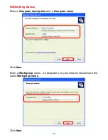
Page 26: ...26 Networking Basics Enter a Computer description and a Computer name Click Next Enter a Workgroup name All computers on your network should have the same Workgroup name Click Next ...

Page 27: ...27 Networking Basics Please wait while the wizard applies the changes When the changes are complete click Next Please wait while the wizard configures the computer This may take a few minutes ...

Page 28: ...best option In this example Create a Network Setup Disk has been selected You will run this disk on each of the computers on your network Click Next Insert a disk into the Floppy Disk Drive in this case drive A Format the disk if you wish and click Next ...

Page 29: ...s the files Please read the information under Here s how in the screen below After you complete the Network Setup Wizard you will use the Network Setup Disk to run the Network Setup Wizard once on each of the computers on your network To continue click Next ...

Page 30: ...settings will take effect when you restart the computer Click Yes to restart the computer You have completed configuring this computer Next you will need to run the Network Setup Disk on all the other computers on your network After running the Network Setup Disk on all your computers your new wireless network will be ready to use ...

Page 31: ...indows XP Click Start in the lower left corner of the screen Right click on My Computer Select Properties and click Select the Computer Name Tab in the System Properties window You may enter a Computer description if you wish this field is optional To rename the computer or join a domain Click Change ...

Page 32: ... the IP Address in Windows XP 2000 Go to Start All Programs Accessories Command Prompt In this window enter the Computer name Select Workgroup and enter the name of the Workgroup All computers on your network must have the same Workgroup name Click OK ...

Page 33: ...ompt All the configuration settings are displayed as shown below Type ipconfig renew at the prompt to get a new IP Address shown below Windows 98SE Me users go to Start Run Type Command Type winipcfg at the prompt Click Release and Renew to obtain a new IP Address D Link Air DWL 650 Wireless Cardbus Adap ...

Page 34: ...twork using DHCP Dynamic Host Configuration Protocol technology If you are using a DHCP capable Gateway Router you will not need to assign Static IP Addresses If you are not using a DHCP capable Gateway Router or you need to assign a Static IP Address please follow these instructions Go to Start Double click on Control Panel Double click on Network Connections ...

Page 35: ...35 Networking Basics Assigning a Static IP Address Right click on Local Area Connections Click Properties Highlight Internet Protocol TCP IP Click Properties D Link Air DWL 510 Wireless Adapter ...

Page 36: ...tween 192 168 0 3 and 192 168 0 254 No two computes can have the same IP Address The subnet mask must be the same for all the computers on the network Input your DNS server address only if you plan to use the Internet Note If you are entering a DNS server address you must also enter the IP Address of the Default Gateway The DNS server information will be provided by your ISP Internet Service Provi...

Page 37: ...Wireless Router or Access Point A good wireless connection will show four replies from the wireless router or access point as shown For Windows Me and 98SE Go to Start Run type command A window similar to this will appear Type ping xxx xxx xxx xxx where xxx is the IP address of the Wireless Router or Access Point A good wireless connection will show four replies from the wireless router or access ...

Page 38: ... printer connected to your network through a Gateway Router use the Add Printer Wizard Please follow the directions below First make sure that you have run the Network Setup Wizard on all of the computers on your network We will show you 3 ways to use the Add Printer Wizard 1 Adding a local printer 2 Sharing a network printer 3 Sharing an LPR printer 1 Adding a local printer A printer connected di...

Page 39: ...39 Networking Basics Adding a local printer Click on Add a printer Click Next ...

Page 40: ...n selected Click Next Select Use the following port From the pull down menu select the correct port for your printer Most computers use the LPT1 port as shown in the illustration Click Next Select and highlight the correct driver for your printer Click Next If the correct driver is not displayed insert the CD or floppy disk that came with your printer and click Have Disk ...

Page 41: ...s screen you can change the name of the printer optional Click Next Select Yes to print a test page A successful printing will confirm that you have chosen the correct driver Click Next This screen gives you information about your printer Click Finish ...

Page 42: ...asics Adding a local printer When the test page has printed Go to Start Printers and Faxes A successful installation will display the printer icon as shown at right You have successfully added a local printer Click OK ...

Page 43: ...etup Wizard on all the computers on your network you can run the Add Printer Wizard on all the computers on your network Please follow these directions to use the Add Printer Wizard to share the printer on your network Go to Start Printers and Faxes Click on Add a Printer Click Next ...

Page 44: ...44 Networking Basics Sharing a network printer Select Network Printer Click Next Select Browse for a printer Click Next ...

Page 45: ...45 Networking Basics Sharing a network printer To check for proper installation Select the printer you would like to share Click Next Click Finish Go to Start Printers and Faxes ...

Page 46: ...ed adding the printer To share this printer on your network Remember the printer name Run the Add Printer Wizard on all the computers on your network Make sure you have already run the Network Setup Wizard on all the network computers After you run the Add Printer Wizard on all the computers in the network you can share the printer ...

Page 47: ... Server such as the DP 101P Please make sure that you have run the Network Setup Wizard on all the computers on your network To share an LPR printer please follow these directions Go to Start Printers and Faxes Click on Add a Printer The screen to the right will display Click Next Select Local Printer Click Next ...

Page 48: ...n LPR printer Select Create a new port From the pull down menu select Standard TCP IP Port as shown Click Next Please read the instructions on this screen Click Next Enter the Printer IP Address and the Port Name as shown Click Next ...

Page 49: ...g an LPR printer In this screen select Custom Click Settings Enter the Port Name and the Printer Name or IP Address Select LPR Enter a Queue Name If there is more than one port on the print server you must name the Queue Click OK ...

Page 50: ...w you information about your printer Click Finish Select the printer you are adding from the list of Printers Insert the printer driver disk that came with your printer Click Have Disk If the printer driver is already installed Select Keep existing driver Click Next ...

Page 51: ...e other computers on your network Click Next Select Yes to print a test page Click Next This screen will display information about your printer Click Finish to complete the addition of the printer Please run the Add Printer Wizard on all the computers on your network in order to share the printer Note You must run the Network Setup Wizard on all the computers on your network before you run the Add...

Page 52: ...ations Standards IEEE 802 11b WiFi Certified Adapter Type 32 bit PCI slot System Requirements PC Computer with 32 bit PCI Slot Supported Operating Systems Windows XP WHQL Windows 2000 Windows Me Windows 98SE Data Security 64 or 128 bit WEP Wired Equivalent Privacy Encryption Data Rate Mbps channel 11 CCK 5 5 CCK 2 QPSK 1 BPSK Key Management Automatic Dynamic Key Allocation ADKA through public key ...

Page 53: ... via Access Points with Roaming Antenna Dipole with detachable reverse SMA connector Frequency Range 2 4 2 4835 GHz Direct Sequence Spread Spectrum DSSS Operating Channels 1 11 United States FCC 1 11 Canada DOC 1 14 Japan MKK 1 13 Europe Except Spain and France ETSI Physical Dimensions L 4 75 inches 120 mm W 2 28 inches 58 mm H 6 inches 2 mm Temperature Operating Temperature 14ºF to 131ºF 10 C to ...

Page 54: ...y period on this product U S customers can contact D Link technical support through our web site or by phone D Link Technical Support over the Telephone 877 453 5465 24 hours a day seven days a week D Link Technical Support over the Internet http support dlink com When contacting technical support please provide the following information Serial number of the unit Model number or product name Softw...

Page 55: ...k s then current functional specifications for the Software as set forth in the applicable documentation from the date of original retail purchase of the Software for a period of ninety 90 days Warranty Period provided that the Software is properly installed on approved hardware and operated as contemplated in its documentation D Link further warrants that during the Warranty Period the magnetic m...

Page 56: ...d cosmetic damage Any hardware software firmware or other products or services provided by anyone other than D Link Products that have been purchased from inventory clearance or liquidation sales or other sales in which D Link the sellers or the liquidators expressly disclaim their warranty obligation pertaining to the product Repair by anyone other than D Link or an Authorized D Link Service Offi...

Page 57: ...arantee that interference will not occur in a particular installation If this equipment does cause harmful interference to radio or television reception which can be determined by turning the equipment off and on the user is encouraged to try to correct the interference by one or more of the following measures Reorient or relocate the receiving antenna Increase the separation between the equipment...

Reviews: