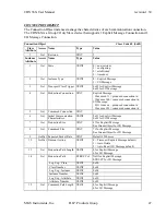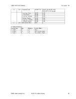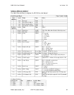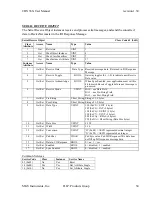
CDN36X User Manual
revision 1.30
Chapter 6 – RSNetworx
™
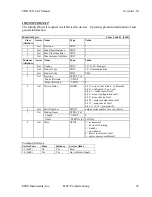
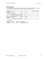
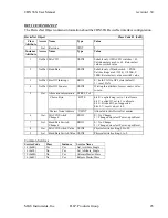
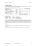
Configuration Example
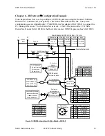
This chapter shows how to set up configure a CDN366 gateway using the Rockwell Software
RSNetworx
™
software and your gateway’s Electronic Data Sheet (EDS) file. The system
configuration uses an Allen-Bradley 1770-KFD DeviceNet adapter (MAC ID 62) to connect the
PC running RSNetworx
™
to the DeviceNet network. A SLC500 system with a 1747-SDN
DeviceNet Scanner (MAC ID 00) is the DeviceNet master. CDN366 gateway has MAC ID 03.
Comm.
Comm.
GND
DeviceNet network
24VDC Power Supply
+
120VAC
24VDC
--
GND
Pin
1
RS232 serial
3
communication
5
Pin
1
2
3
4
5
Pin
Pin
Pin
2
7
4
3
1
3
8
5
2
5
3
1
2
4
5
Figure 1. CDN366 Integrate with Allen Bradley SLC500
PS to DeviceNet Dist.
Color
Description
red
BUS+ (24vdc)
Func.
Func.
9 pin DIN RS232 Serial
Interface to Barcode
Reader, Scanner
Weigh Scale or etc.
To PC RS232 9 pin
Serial Interface For
Used with RSLinx,
& RSNetW orx Prog.
V- (BUS-)
data high (CAN H)
Male Connector
DeviceNet
Color
Description
clear
red
shield (Drain)
V+ (BUS+)
blue
data low (CAN L)
Fuse 1A
Fuse 6A
RXD
TXD
GND
RTS
CTS
DeviceNet Connector
black
white
to pin 1 DeviceNet connector
black
clear
data high (CAN H)
V+ (BUS+)
Terminal Connector
BUS- (0vdc)
Shield (Drain)
white
Description
red
V- (BUS-)
data low (CAN L)
shield (Drain)
black
blue
clear
CDN366
RS232-DeviceNet
DeviceNet
Gateway Module
PC Interface
Color
to pin 5 DeviceNet connector
1770-KFD
RS232-DeviceNet
PC Interface Mod.
DIP790 Device
Net Dist. Board
Slot 3
Power Sup.
Slot 2
8 pt. Input
Slot 0
120/240VAC
Slot 1
1747-L524
DeviceNet
Scanner
1747-SDN
Input
SLC502
PLC CPU
Fuse 3A
24vdc output
1747-P1
Allen Bradley SLC500 4 Slot Rack, 1746-A4
N
L
Neutral
module
1746-IV8
8 pt.Output
module
1746-OB8
120VAC
Pin 1,4,6,9 are unused
1747-PIC
RS232-PLC
Module
RS232 Pin Layout
To PC RS232 25
Pin Serial Interface
For Used with
RSLogic Prog.
MKS Instruments, Inc.
D.I.P. Products Group
52


