CDN36X User Manual
revision 1.30
Input File
Inputs
DeviceNet I/O Response
input data
Receive
Message Packet
Outputs
Output File
DeviceNet I/O Command
output data
Transmit
Message Packet
DeviceNet
Master
CDN36X
Serial
Device
Gateway
Application
Program
DeviceNet network
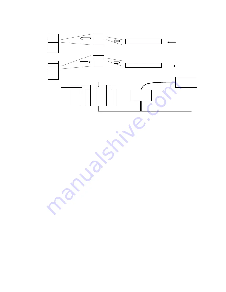
The first 2 output data bytes received from the DeviceNet master contain synchronization bits for
the gateway transmit and receive operations. The remaining output data bytes contain serial
message data to be transmitted out the serial channel. Up to 8 different output data values can be
sent in an I/O Command Message, one for each enabled
Serial Transmit Object
Instance.
The first 2 input data bytes sent from the gateway contain synchronization bits for the gateway
transmit and receive operations. The remaining input data bytes contain serial message data that
has been received and processed by the gateway. Up to 8 different input data values can be
returned in an I/O Response Message, one for each enabled
Serial Receive Object
Instance.
The following diagram shows how the gateway’s input and output data bytes map into the
DeviceNet I/O Response and I/O Command Messages. The diagram includes all 8
Serial
Receive Object
Instances and 8
Serial Transmit Object
Instances. If an instance is not enabled, its
data bytes are not mapped or present in the corresponding I/O Message. The total number of
input or output data bytes required for each Instance is defined by its configuration.
The gateway supports a maximum of 128 data bytes for all 8
Serial Receive Object
Instances and
128 bytes for all 8
Serial Transmit Object
Instances, regardless of whether an instance is enabled
or not. Unused instances should have their data size set to the smallest number of bytes.
MKS Instruments, Inc.
D.I.P. Products Group
11


