background image

8/20

RZN 4416-M    Rev.:1.1

Gesamtstrom /

total consumption

0,5

1

1,5

2

2,5

3

3,5

4

4,5

5

5,5

6

6,5

7

7,5

8

8,5

9

9,5

10

3x 1,5mm²

240 120

80

60

48

40

34

30

26

24

21

20

18

17

16

15

14

13

13

12

m

3x 2,5mm²

400 200 130

100

80

65

55

50

44

40

36

33

30

28

26

25

24

22

21

20

m

*5x 2,5mm²

800 400 260

200 160 130

110

100

88

80

70

65

60

56

52

50

47

44

42

40

m

**7x 2,5mm²

1200 600 390

300 240 200

170

150 130 120

110

100

92

85

80

75

71

67

63

60

m

Detector Cables (Line):

The detector cables are monitored for short
circuit and for break.
The opening device is automatically
triggered and opens up in case of fault, when
DIP-switch 7 is on ON.
Smoke vent button cable and cable of
automatic detectors:
- weak current sheathed flexible cable YR
   6 x 0.8

or

- house wiring cable IY(ST)Y 4 x 2 x 0.6

Cables through areas not monitored:

An increased time of functioning of the cable
can be required, when drive lines are installed
through building parts, which are not monitored.
- Safety line with functional conservation

... E90, according to DIN 4102* or standard
guidelines for line systems MLAR.

(see supplementary sheet 1 to DIN VDE

   0108)

* Notice: No type designation is given

for these cables, because of a large

  variety on the market. Please consult
  your D+H distributor about these.

The smoke vent control panel is designed
for opening smoke vent devices, which
operate by thermal ascending force and by
automatic fire recognition devices  (thermal
detector, smoke detector), and they release
either self-acting or manual by smoke
detectors at an early stage of a fire, and
remain in opened position without further
power consumption. In these cases,
functioning preservation of the electrical line
system is required only at an early stage of
fire. Protected wiring is required with
protection against mechanical damages
according to DIN 18232 section 2.5.5
paragraph 4.

Control Cables (Group):

Cables from the smoke vent control panel to
connection of drive (drive lines have a
monitoring wire, in which fire recognition
devices (thermal maximal detector e.g. THE)
can be looped-in):
- Safety line, with functional conservation

... E30, according to DIN 4102* or standard
guidelines for line systems MLAR.

Cables for D+H Smoke and Heat Vent Systems

cross section (mm²) = plain cable length (m) x total current

80

* Connect in parallel 2 wires for each drive line.

Line lengths and Cross sections:

Number of wires and cross-sections indicated, refer to required lines only. In case of
using a line with earthed conductor (green/ yellow), this one will not be counted in and
must not be wired.

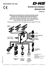
Summary of Contents for RZN 4416-M

Page 1: ...orized by the manufacturer Green control diodes in the buttons must constantly lighten otherwise see Informations for Starting Repair power failure at once Emergency power supply for 72 hours drive gr...

Page 2: ...Maintenance Guarantee Piktograph explanation 2 Technical Data Accumulator Control TID 3 Introduction 4 View motherboard RZN 4416 K 5 Drives and smoke vent buttons 6 Wiring plan 7 Connection cables 8...

Page 3: ...al discharge of accumulator the control panel will switch off In this case smoke vent is no longer ensured In this case a malfunction will be no more indicated either Technical Data Rated voltage 230...

Page 4: ...Insurer against damage of property VdS and the respective local authorities Recommended is that maintenance work should be carried out by authorized specialist companies only Only regular and profess...

Page 5: ...reset indicator fuse accumulator accumulator connection LED failure accumulator charging voltage control accumulator fire recognition element thermo maximum signal ground short DIP switch S6 control p...

Page 6: ...hat an escape must not be hindered by the window wing itself by structural facts like offsets or the like Minimum ventilating surface is given by le gal regulations and structural facts The smoke vent...

Page 7: ...mer Fire detector 24VDC FO 1362 or FT 1262 Wiring Plan Paragon 230 V Supply Provide for separate electric circuit Mark fuses Plug covering cap over mains binder on motherboard of control panel Connect...

Page 8: ...ause of a large variety on the market Please consult your D H distributor about these The smoke vent control panel is designed for opening smoke vent devices which operate by thermal ascending force a...

Page 9: ...ector THE 4 RZN 4416 M RM MOT branch box Length of line and cross sections see page 12 last RT 43 N 10kW alarm control line line malfunction closed 2 7 8 3 1 6 4 line control alarm closed 2 3 1 6 4 7...

Page 10: ...4 5 6 7 8 RZN 4416 M line control alarm closed RM RT Smoke vent button RT 43 H Smoke vent button RT 43 N 10kW alarm alarm control control line line line line malfunction closed closed 2 2 7 8 7 3 3 1...

Page 11: ...vent button lane 2nd RT 43 H RT 43 H RT 43 N RT 43 N 10kW alarm alarm control control line line line line malfunction malfunction closed closed 2 2 7 7 8 8 3 3 1 1 6 6 4 4 alarm alarm zu zu red red gr...

Page 12: ...losed open signal optional N open monitoring Mot a Mot b 5 6 7 1 2 3 4 1 1 2 2 optional RM RT LT 3 4 5 6 7 8 line control alarm closed external excitiation vent button LT 43 SD fire detector Typ opera...

Page 13: ...e vent button 1st lane RT 42 Smoke vent button 2nd lane RT 42 10kW RT 42 RT 42 line line line control control control alarm alarm alarm closed closed closed 7 7 7 2 2 2 3 3 3 1 1 1 6 6 6 4 4 5 4 OK OK...

Page 14: ...ctor dependency are employed Connection of several fire detectors Connection of one fire detector N N Z M1 M2 D1 D2 interrupter key magnetic clamp terminal resistor line 10K single fire detector 180R...

Page 15: ...a Mot b derive off in par allel monitoring will be looped through all cables up to group end Example 1 1 lane Simple installation but unfavourable for voltage drop All drives on one line Example 2 2 l...

Page 16: ...special conditions only Performance check alarm reset and ventilation 10k resistance in smoke vent button 10k resistance in fire detector Stop module 2x47k in conduit box Connect mains mains control l...

Page 17: ...e limitation be retriggered again Switch 4 on ON Storage operation in CLOSED direction Switch 4 on OFF Key operation in CLOSED direction Switch 5 on ON Storage operation in OPEN direction Switch 5 on...

Page 18: ...n idle idle idle Bus control Switch 1 on ON Two smoke detectors dependency Attention Switch Smoke detector alarm can be reset only in control panel Dip switch 2 must be switched on OFF when remote res...

Page 19: ...on Ventilating time limitation OPEN retriggering Duty cycle in CLOSED direction Duty cycle in OPEN direction Group CLOSED in case of alarm Group fault on alarm Alarm re clocking OPEN running time limi...

Page 20: ...tector Reset line in control panel switch off switch on press button red display diode extinguishes in button and control panel Press masked button in smoke vent button Smoke vent must be closing The...

Reviews: