background image

17/20

RZN 4402/04-K

Rev.:3.8

M

M

Z

ent

r

a

l

e

A

b

z

we

ig

dose

A

b

z

we

ig

dose

a

m M

oto

r

we

i

te

r

e

A

b

z

we

ig

e

gl

e

i

cha

r

t

ig

scha

l

ten

A

b

z

we

ig

dose

a

m M

oto

r

A

b

z

we

ig

dose

b

r.

b

r.

b

l.

b

l.

7

6

5

M

M

M

M

M

M M M

3

x

2,5

²

25

m

M M M M

M M M M

4x

2,5

²

3

x

2,5

²

50

m

50

m

M

M

M

M

M

M M M

3

x

2,5

²

4x

2,5

²

4

0

m

75

m

M M M

M

M

M M M

4x

2,5

²

5

x

2,5

²

75

m

75

m

200

m

control panel

branch box

connect in the
same way further
derivations

branch box

branch box
at drive

branch box
at drive

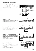
Connection Examples

Connection with line derivation:

supply wires 

Mot a / Mot b

 derive off in  par-

allel, 

monitoring 

will be looped through all

cables up to group end.

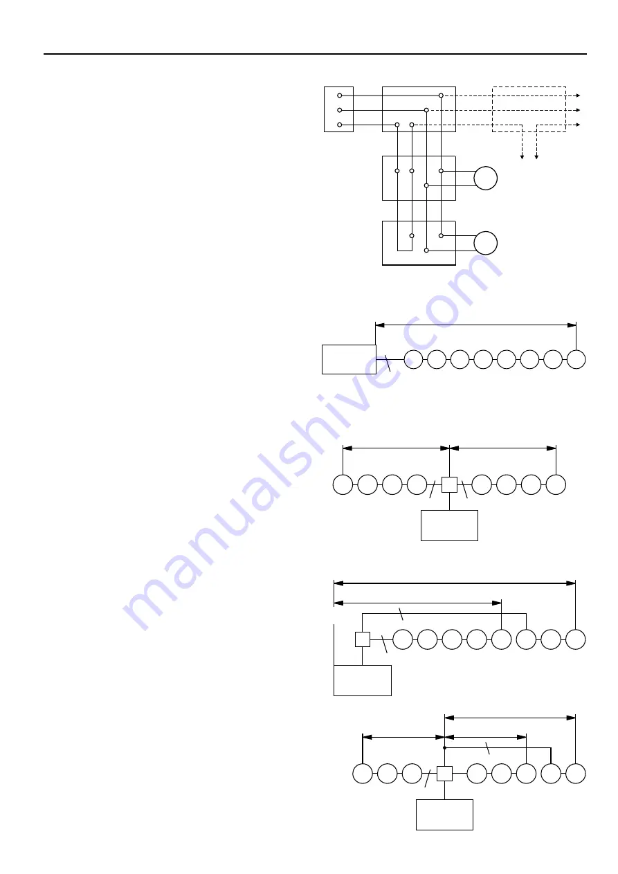
Example 1:

  1 line

Simple installation, but unfavourable for
voltage drop: All drives on one line.

Example 2:

  2 lines

Control panel in centre, one side wired as
derivation, the other as terminal line.
Observe 4 wires for derivation!

Example 3:

  2  lines on one side

Derivation and terminal lines in same
direction; number of drives vary according
to length of line.
Observe 4 wires for derivation!

Example 4:

  3 lines

3 lines are installed due to extremely long
distances: 2 lines with 3 drives each on 75
m line as derivation, and 1 line with 2 drives
on 200 m line.
Observe 4 wires for derivation!

Summary of Contents for RZN 4402-K

Page 1: ...by the manufacturer Green control diodes in the buttons must constantly lighten otherwise see Informations for Starting Repair power failure at once Emergency power supply for 72 hours Approval Numbe...

Page 2: ...y the latest maintenance instructions Following tests must be carried out in the course of maintenance Outside examination inspection of system components Measuring of insulation resistances Checking...

Page 3: ...ation of German Insurer against damage of property VdS and the respective local authorities Recommended is that maintenance work should be carried out by authorized specialist companies only Only regu...

Page 4: ...nts Retrofitable System Overview Drive group signal indicating board acoustical optical alarm devices signal contact 230V 50Hz Mains supply wind rain transmitter smoke vent button min 2 piece ventilat...

Page 5: ...x 262 x 81mm Mounting of housing 1 joint rod door plaster cross for flush mounting cable cover cable bushing only surface mounting housing flush mounted wall hook optional flush mounted set UPS 44 K n...

Page 6: ...of fire walls must not be inadmissibly influenced Sound insulation is impaired by flush mounting Final mounting 3 Mount and connect central pcb 4 Screw down cable cover 5 Unhinge door of the door fra...

Page 7: ...n cover plate in control panel View motherboard RZN 4402 04 K fire recognition element thermo maximum signal fuse drive fuse external detector Dip switch mains conne ction LED failure group LED contro...

Page 8: ...in the ceiling Size kind and arrangement of the opening is of decisive significance for an optimal effect of the smoke and heat vent system The important thing here is that an escape must not be hind...

Page 9: ...H N surface 24 VDC circa 1 5m above upper edge firm flooring by customer 55mm flush socket Vent button 24 VDC e g LT 43 circa 1 2 above upper edge firm flooring at flush type by others 55mm flush sock...

Page 10: ...e by thermal ascending force and by automatic fire recognition devices thermal detector smoke detector and they release either self acting or manual by smoke detectors at an early stage of a fire and...

Page 11: ...pinched in control panel for transport Take it off there and connect according to plan Terminal resistors must remain at binder RM 1 2 when no fire detector or external control exists Fire detectors...

Page 12: ...12 20 RZN 4402 04 K Rev 3 8 Parallel Connection of Smoke Vent Buttons RT 42...

Page 13: ...re pinched in control panel for transport Take it off there and connect according to plan Terminal resistors must remain at binder RM 1 2 when no fire detector or external control exists Fire detector...

Page 14: ...02 04 K line line control alarm close RM RT smoke vent button RT 43 H smoke vent button RT 43 N 10kW 10kW alarm alarm control control line line line line malfunction close close 2 2 7 8 7 3 3 1 1 6 6...

Page 15: ...15 20 RZN 4402 04 K Rev 3 8 Parallel Connection of 2 x 2 Smoke Vent Buttons RT43 H N...

Page 16: ...Magnetic clamp The resistor must not be used when line connections with 2 detector dependency are employed Connection of several fire detectors Connection of one fire detector terminal resistor line 1...

Page 17: ...wires Mot a Mot b derive off in par allel monitoring will be looped through all cables up to group end Example 1 1 line Simple installation but unfavourable for voltage drop All drives on one line Exa...

Page 18: ...be reset under special conditions only Performance check alarm reset and ventilation 10k resistance in smoke vent button 10k resistance in fire detector Stop module 2x47k in conduit box Connect mains...

Page 19: ...ossible then If Dip switch 5 is on OFF the function power failure CLOSED will be ineffective see Dip switch 4 Dip switch 6 on ON Ventilation flap opens up to final position by single pressing on vent...

Page 20: ...red display diode extinguishes in button and control panel Smoke vent must close Automatic fire detectors Release smoke detector individual by D H smoke detector tester as an alternative by cigarette...

Reviews: