CPS-B1
CPS-B1
99.828.32 1.4/07/21
99.828.32 1.4/07/21
18/
24
19/
24
English
English
Once a year by a specialist company, who is
authorized by the appliance manufacturer.
Renew test badge, keep log book.
The respective current D+H maintenance
instruction is decisive.
D+H authorized expert companies have been
specially trained by D+H for carrying out expertly
this maintenance, and they get automatically the
latest maintenance instructions.
Maintenance
Following tests must be carried out in the course of
maintenance:
- Outside examination / inspection of system
components
- Checking of all relevant power supply units
- Functional testing of connected system
components
- Record of competent carrying-out of
maintenance, and designation according to
directions
Inspection
Regular visual inspection between maintenance by the operator or a trained person.
Immediately correct any defects.
Indicators:
-
Green LEDs
in the buttons must
illuminate
.
-
Yellow LEDs
in the buttons and the control panel
are
not allowed to illuminate or flash
(fault).
- If the green LEDs do not illuminate or if the
yellow LEDs illuminate or flash, contact After
Sales service.
Examination:
- Check all appliances and cable connections for
outer damage and dirt accumulation.
- Fire detectors, smoke vent buttons, smoke vents
and so on must not be impaired in their function
by goods in storage or structural changings.
Inspection and maintenance has to be carried out
according to D+H maintenance notes. Only original
D+H spare parts may be used. Repair is to be
carried out exclusively by D+H.
Wipe away debris or contamination with a dry, soft
cloth.
Do not use cleaning agents or solvents.
Repair and cleaning
Electrical devices, accessories, batteries and packa-
ging should be sorted for environmental-friendly
recycling. Do not dispose electrical devices and
batteries into household waste!
Only for EC countries:
According the European Guideline 2012/19/EU for
waste electrical and electronic equipment and its
implementation into national right, electrcal devices
that are no longer usable must be collected separa-
tely and disposed of in an environmentally correct
manner.
Disposal
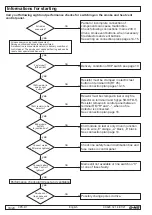
Informations for starting
Carry out following sight and performance checks for switching-on the smoke and heat vent
control panel.
All cables
connected?
Factory set?
(DIP switch)
10k
Ω resistor in
smoke vent
button
?
End module
2x47k
Ω
in junction box?
Connect mains.
LED mains lightens?
Connect battery
lines. Control l
ightens?
Smoke vent
flap opens and
closes?
All necessary moving loads connected?
Smoke vent components are line-monitored.
A malfunction is connected as alarm in delivery condition of
control panel. The smoke vent opens self-acting and can be
reset under special conditions only.
yes
yes
yes
yes
yes
yes
yes
Performance check alarm/reset and ventilation
yes
Partial or incomplete connection of
components can cause malfunction.
Check following connections: mains 230 V,
drives, smoke vent buttons, when necessary
fire detectors and vent buttons.
See wiring an connection plans pages 14-15.
Delivery condition of DIP switch see page 10.
Resistor must be cramped in electric last
button on terminal 3/8 (RT 45).
See connection plan pages 14-15.
Resistor must be cramped in last or only fire
detector on terminal 3 and 5 (type SD-O/FD-T).
Resistor remains in control panel between
terminal RM "R" and "–", when no fire
detector is connected.
See connection plan page 16.
10k
Ω resistor in fire
detector?
yes
End module on last or only drive in junction
box on wire „E“ orange, „a“ black, „b“ black.
See connection plan page 14.
Check line safety fuse in distribution box and
fuse mains in control panel.
Mains still not available or line switch on "0"
or one of fuses faulty.
Possibly change poles in drive.
no
no
no
no
no
no
no
no

