background image

CPS-B1

CPS-B1

99.828.32 1.4/07/21

99.828.32 1.4/07/21

10/

24

11/

24

DIP switch settings 

Delivery state

ON

1

2

3

4

5

6

7

8

ON

1

2

3

4

5

DIP switch S1
S1.1

Line fault = alarm
ON

In case of a line fault (e.g. at an interrupted detector line or short circuit) the control 
panel will be switched on alarm, that means the smoke vent opens.

S1.2

Group fault = alarm
ON

In case of a group fault (e.g. in case of an interrupted monitoring line) the control panel 
will be switched on alarm, that means the smoke vent opens. 
DIP switch must be on ON in conjunction with a ground in thermal maximal detector 
(e.g. THE4).

S1.3

Deactivate remote reset detector line
ON

Smoke detector alarm can not be reset by single pressing on the button "close SHEV" 
in the smoke vent button.

OFF Smoke detector alarm will be reset by pressing on the button "close SHEV" in the 

smoke vent button.

S1.4

Closing group in case of alarm
ON

In case of power failure the drives will close.

S1.5

SHEV retriggering
ON

The smoke vent is triggered for a duration of 30 minutes in intervals of 2 minutes 
according to VdS 2581.

S1.6

Power failure "CLOSE"
ON

In case of power failure the drives will close automatically. 
Caution: Danger of crushing! The drives close automatically.

S1.7

Extended line monitoring of the group
ON

All wires to the drives are monitored in all states.

S1.8

Operation without battery
ON

The charging and monitoring of the batteries is deactivated.

DIP switch S2
S2.1

Storage operation OPEN
ON

Drives OPEN up to final position by single pressing on vent button.

OFF Drives are opening only so long as the vent button is pressed.

S2.2

Storage operation CLOSE
ON

Drives CLOSE up to final position by single pressing on vent button

OFF Drives are closing only so long as the vent button or the button "close SHEV" in the 

smoke vent button is pressed.

S2.3

Ventilation time limitation
ON

The drives will automatically close again after the ventilation time set (Factory setting: 
10 min., adjustable via SCS software)
Caution: Danger of crushing! The drives close automatically.

S2.4

Reset with alarm pending
ON

A permanently present alarm on the RM line or the FAS input can be suppressed by a 
reset. If such an alarm is still present after a reset, the red LED in the smoke vent 
button flashes to indicate that it is being suppressed.

S2.5

Lamp test

ON -
OFF

Actuate the DIP switch (ON/ OFF). All LEDs on the motherboard are switched on 
continuously for 10 seconds (except for the mains OK LED, which is lit as long as the 
mains voltage is present). 

Line lenghts and cross sections

0,5

240
400

1

120
200

1,5

80

130

2

60

100

2,5

48
80

3

40
65

3,5

34
55

4

30
50

m
m

Total current

 3 x 1,5 mm²
 3 x 2,5 mm²

5

24
40

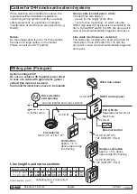
Cables for D+H smoke an heat vent systems

When selecting and installing the cables, the 
regional electrical installation regulations 
concerning wiring systems and the necessary 
safety equipment, or guidelines on integrity 
maintenance of electric lines are observed (e.g. 
MLAR).

Notice:

No type designation is given  for these cables, 
because of a large variety on the market.
Please consult your D+H partner.

Wiring plan (Paragon)

Cross section  (mm²) =

Cable lenght (m) x Total current 

80

Group cable (control panel - drive)

At least three wire design:
- 2 wires for the supply of the drive
- 1 wire for line monitoring, on which also the 
SHEV high speed (HS) signal is transmitted to the 
drive. If group DIP switch 8 is ON, the group will in 
case of a fault automatically triggered and opens.

Line cable (control panel - detector)

The cables are monitored for short circuit and for 
interruption. If line DIP switch S1.1 is ON, the 
group will in case of a fault automatically triggered 
and opens.

230 V, 50 Hz

Seperate electric circuit.
Mark fuse.

to further ones

see line lenghts and cross sections

Drive at smoke 
vent opening

SHEV control panel

Vent button 

approx. 1,2 m 
above upper edge 
firm flooring

Smoke vent button

approx. 1,5 m above 
upper edge firm flooring

External control

4x 0,8 Ø

6x 0,8 Ø (RT 45)
10x 0,8 Ø (RT 45-LT)

6x 0,8 Ø (RT 45)
10x 0,8 Ø (RT 45-LT)

2x 0,8 Ø

2x 0,8 Ø

OK

OK

Wind rain sensor

3x 0,8 Ø

System voltage 24 V!
Do not run cables with together power lines!
In case of a cable with ground wire (green / 
yellow) this must not be used!
Cable and terminal boxes have to be labeled.

Fire detector

SD-O 371 or FD-T 271

English

English

Summary of Contents for CPS-B1

Page 1: ...CPS B1 99 828 32 1 4 07 21 en Table of contents Page 2 Original instructions Page 3...

Page 2: ...t 9 DIP switch settings 10 Cables for D H smoke an heat vent systems 11 Wiring plan Paragon 11 24 V Emergency supply 12 230 V Power supply 13 Connection overview 14 Connection of smoke vent buttons 15...

Page 3: ...sively by trained and experienced fitters in compliance with the technical guidelines and specifications Personal handover and training for users is included Maintenance and repair Every building oper...

Page 4: ...will start flashing A malfunction of the smoke vent system will be still indicated by the extinction of the green LED in the smoke vent button After the maintenance time is expired approx 14 to 16 mon...

Page 5: ...cisive significance for an optimal effect of the smoke and heat vent system These requirements are defined in the relevant regulations of the respective country More informations are also available un...

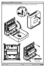
Page 6: ...CPS B1 99 828 32 1 4 07 21 6 24 Mount control panel sheltered and easily accessible for maintenance in proximity of drive Mounting of SHEV control panel max 5 mm not included 4x English...

Page 7: ...8 ON 1 2 3 4 5 Jumper clamp holder WAGO clamp 221 not included Jumper clamp holder WAGO clamp 243 not included Overview 4x 5x 35 mm top hat rail for extension modules up to 29 mm width Document stora...

Page 8: ...fire in immediate vicinity of the mounting place the entire smoke and heat vent system will be emergency opened under alarm conditions SHEV alarm Fault Mains existing Pictogram explanation D H window...

Page 9: ...X5 X5 1 FE Shield connection for fire detector cable X5 2 R Input fire detector triggering monitoring X5 3 Reference potential X5 4 T Input smoke vent button triggering monitoring X5 5 Reference poten...

Page 10: ...Danger of crushing The drives close automatically S1 7 Extended line monitoring of the group ON All wires to the drives are monitored in all states S1 8 Operation without battery ON The charging and...

Page 11: ...g on which also the SHEV high speed HS signal is transmitted to the drive If group DIP switch 8 is ON the group will in case of a fault automatically triggered and opens Line cable control panel detec...

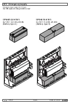
Page 12: ...4 07 21 12 24 24 V Emergency supply Emergency power supply for 72 hours Use VdS approved storage batteries only CPS B1 2 5 0101 2x 12V 2 2 Ah 0 3Ah Battery type 2 CPS B1 5 0101 2x 12V 3 4 Ah 0 3Ah Bat...

Page 13: ...CPS B1 99 828 32 1 4 07 21 13 24 230 V 50 Hz Seperate electric circuit Mark fuse 230 V Power supply Funtional earth FE L N PE English...

Page 14: ...D LT X3 L Z LT 84 U SD L P OK 2 8 3 1 6 4 7 5 RT 45 2 8 3 1 6 4 7 5 RT 45 2 8 3 1 6 4 7 5 OK Line T R FE K A Z S Line Control Alarm CLOSE RM X5 10kW Fault Alarm Control Line CLOSE Fault n c RT X5 10kW...

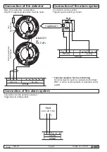
Page 15: ...1 6 4 7 5 RT 45 2 8 3 1 6 4 7 5 OK 2 8 3 1 6 4 7 5 RT 45 2 8 3 1 6 4 7 5 RT 45 Line n c Fault Line Control Alarm CLOSE Alarm Control Line Line CLOSE Fault Alarm Control Line CLOSE Fault n c 10kW 2 8 3...

Page 16: ...FE B B RS L CPS B1 RM X5 LE X6 first to penultimate fire detector last fire detector SD O 371 or FD T 271 R E P 6 EM 2 1 C 3 I N 4 OUT 5 E P 6 EM 2 1 C 3 I N 4 OUT 5 10 kW T R FE K A Z S CPS B1 RM X5...

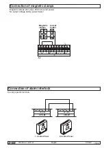
Page 17: ...netic clamps Magnetic clamps 24V max 250 mA overall power No output voltage during power failure Cutout button Magnetic clamps B B RS L CPS B1 LE X6 B B RS L CPS B1 LE X6 1 Control Panel 2 Control Pan...

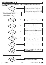
Page 18: ...mplete connection of components can cause malfunction Check following connections mains 230 V drives smoke vent buttons when necessary fire detectors and vent buttons See wiring an connection plans pa...

Page 19: ...ot allowed to illuminate or flash fault If the green LEDs do not illuminate or if the yellow LEDs illuminate or flash contact After Sales service Examination Check all appliances and cable connections...

Page 20: ...English click OK RAUCHABZUG OK OK RT OK RT OK RT Operation Release in case of alarm External control Manual opening by smoke vent button Automatic opening by fire detector Automatic opening by extern...

Page 21: ...e see DIP switch S1 3 page 10 Emergency closing in case of non resettable alarm With manual release In case of automatic release by fire detector or external control External control or Operation Clos...

Page 22: ...ain Do not ventilate via smoke vent button because otherwise there would be a danger of damage by wind or water The weather automatic can be switched off via an optional automatic switch if gap ventil...

Page 23: ...CPS B1 99 828 32 1 4 07 21 23 24 English...

Page 24: ...28 32 Germany 22949Ammersbek 49 239 Tel 40 605 65 49 Fax 40 605 65 254 E Mail info dh partner com www dh partner com 99 828 32 1 4 07 21 2021 D H Mechatronic AG Ammersbek Rights to technical modifica...

Reviews: