PSoC Analog Coprocessor Pioneer Kit Guide, Doc. # 002-11190 Rev. *B
25
Kit Operation
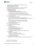
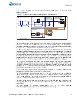
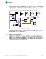
shows the PSoC Creator schematic for interfacing a PIR motion sensor with the PSoC
Analog Coprocessor.
Figure 3-9. Interfacing PSoC Analog Coprocessor with PIR Motion Sensor
The PIR motion sensor implementation on the PSoC Analog Coprocessor Pioneer Kit consists of
five stages: a bias circuit for the PIR motion sensor, a first-stage amplifier, a high-pass filter (HPF), a
second-stage amplifier, and an ADC. In the main stages of the PIR motion sensor implementation,
the two amplifiers are implemented in the PSoC Analog Coprocessor.
The PSoC Analog Coprocessor Pioneer Kit has a dual-element PIR motion sensor (ZRE200GE).
The voltage signal generated by the sensor is AC-coupled (using C48) and clamped to the internal
reference voltage generated from PVref Component. The typical sensor output voltage is in the order
of several millivolts and varies depending on the strength of the incident infrared radiation. To detect
the motion of a human body at a distance of 10 feet, a gain of >1000 is required. A single-stage
amplifier with such a high gain causes the amplifier output to saturate due to the amplification of the
input offset voltage. Thus, a two-stage amplifier is best suited for amplifying with a high gain.
The total gain is split between two stages. The first-stage amplifier uses a noninverting amplifier
configuration using an internal opamp and external gain setting resistors, R118 and R119. The
second-stage amplifier uses a PGA Component. The first-stage amplifier gain is set to 681 and the
PGA gain is set to 1 on startup. However, the second-stage amplifier gain changes depending on the
detection distance required – 3 feet, 10 feet, or 20 feet.
An HPF, made using external passive components C91 and R147, is introduced between the first
and the second amplifier stages to eliminate the offset voltage.
The PIR motion sensor and gain stages use a 1.2-V system bandgap voltage as the reference
voltage. The bandgap voltage is independent of supply voltage fluctuations and hence provides a
stable voltage reference. This voltage is generated using a programmable voltage reference
component, PVref, and is buffered using an opamp.
The output of the second-stage PGA is connected to the Scanning SAR ADC Component. The
Scanning SAR ADC results are compared against threshold values to detect the motion of an IR
emitting object.
For more details of firmware implementation, refer to the Code Example
CE211301_PIR_Motion_Sensing
available in the kit installation directory.


