Installation and Test Operation
FM4 S6E2H-Series Starter Kit Guide, Doc. No. 002-11387 Rev. **
15
2.3 Test Operation
The FM4 S6E2H-Series Starter Kit has been pre-programmed with a test demo code, which
helps you to test all on-board features. The Motorola s-record file,
tp_fm4-120l-s6e2hg.srec
, is
provided in the following directory and can be programmed on the MCU by using the FLASH
MCU Programmer.
<User_Directory>:\FM4 S6E2H-Series Starter Kit_Ver01\Firmware
\Demo Projects\Test_Demo_Code
2.3.1 Run the Test Demo
Follow the instructions to run the test demo code.
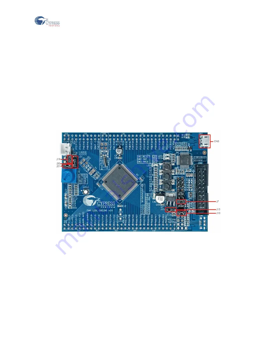
1. Ensure the jumpers J7, J10 and J19 are closed. Close Pin 1 and Pin 2 of J15 and J20.
Close Pin2 and Pin3 of J21 and connect CN3 to a PC using the USB cable provided.
Figure 2-5: Power the Board from CN3
2. Ensure the power LED (LED5) is on and the LED3 blinks with a breathing effect. The RGB
LED (LED2) will alternately flash red, green, and blue.
3. If not already launched, then launch the Serial Port Viewer from the start menu under
All Programs
>
Cypress
>
Serial Port Viewer
.


