background image

Operating Instructions | GPM 450 SPEED


23 


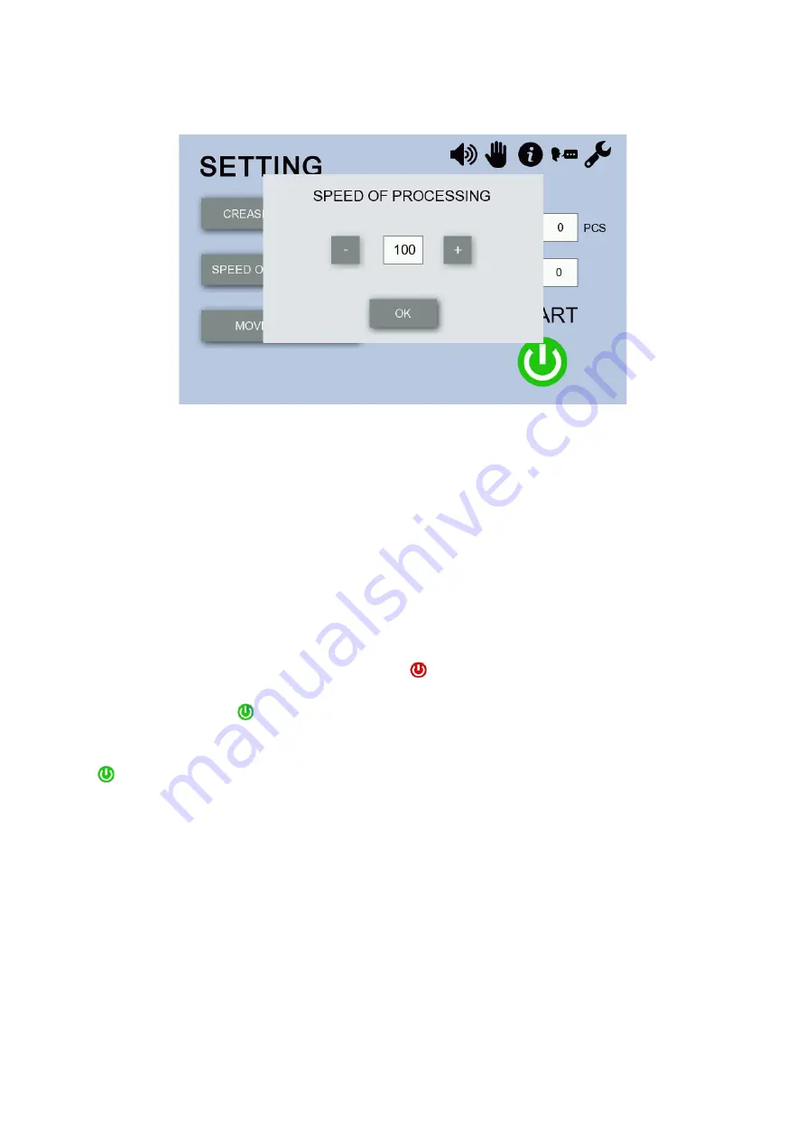
8.4 Setting the Speed of Processing 

Press 

SPEED OF PROCESSING

 on the “SETTING” screen (Fig. 20) to display the following menu. 


Fig. 26: “SPEED OF PROCESSING” Screen


Change speed by using the 

+

 and 

keys. Minimum and maximum values: 50 and 100, respectively. The 

default value is 100, which means 100% speed of the machine (2,500 A4 sheets per hour). The maximum 
speed can be reduced by half. Low speeds are suitable for processing papers complicated to feed or using 
multiple rotary tools on the shaft. When you have finished the setting, press 

OK 

to confirm.


8.5 Setting Batch 

Press the numeric icon next to the field 

BATCH

 on the “SETTING” screen (Fig. 20) to display numeric 

keypad. Use the numeric keypad to set the batch (= the number of sheets to be processed by the machine 
in a single cycle) and press 

ENTER 

to confirm. Enter 

0

 if you wish to switch the batch off. Batch processing 

may be interrupted in three ways: 

1.  The machine is stopped by pressing the 

STOP


 on the touch screen. The touch screen shows 

both the total batch and the number of sheets already processed. When you restart the machine by 

pressing the 

START


, the machine goes on to process the remaining sheets in the batch. 

2.  Press 

STOP

 (8) to stop the machine. The touch screen shows only the total batch and the value 

showing the number sheets already processed in the batch is reset to zero. If you press the 

START


 to restart the machine, the machine processes the batch from the beginning.  

3.  The machine is switched off using the electric switch (12), or by disconnecting the power supply. 

When the machine is switched on again, the batch is not displayed and must be entered anew. 

 
It is also possible to change the batch straight in the Working Screen (Section 8.7, Fig. 29). 

8.6 Program Saving and Loading  

The software allows saving 9 different programs. The values set on the “CREASE POSITION” Screen are 
saved under a program number. Once the feeding and crease position values are set following the 
instructions in Sections 8.3, you can go on to save the program. Press the numeric icon next to the field 

PROGRAM

 on the “SETTING” screen (Fig. 20). The program saving and loading menu (Fig. 27) is 

displayed. Use the 

+

 and 

-

 keys to list values between 

0

 and 

9

. You can save your jobs under 

1 – 9

; value 

0


indicates no program is saved in the memory.  

Summary of Contents for GPM 450 SPEED

Page 1: ...Machine GPM 450 SPEED Warnings This document including the attachments is exclusive intellectual property of Cyklos Choltice producer cooperative Any other use copying distribution or sale is possible...

Page 2: ...Machine Using Touch Screen 19 8 1 Display Unit Preview and SETTING Screen 19 8 2 Overview of Touch Screen Function Icons 19 8 2 1 Sound On Off 19 8 2 2 Manual Control 20 8 2 3 Info 20 8 2 4 Language S...

Page 3: ...Operating Instructions GPM 450 SPEED 3 11 Machine Disposal 30 Appendix 1 Accessories 31 Appendix 2 Instructions for Table Assembly 34 Appendix 3 Optional Accessory 35...

Page 4: ...repair done without authorization can lead to a breach of the warranty We are referring to section 2 2 Work Safety and Health Protection providing basic information about safety during work with the m...

Page 5: ...The owner of the machine is responsible for the machine being operated maintained and serviced only by qualified people The machine design is in compliance with international standards and regulations...

Page 6: ...is forbidden to use the machine outdoors d It is forbidden to use the machine when the electric cord is damaged e It is forbidden to use the machine if it makes strange sounds f It is forbidden to pl...

Page 7: ...ase i Machine dimensions 1250 x 675 x 520 mm j Machine weight net 120 kg gross 157 kg weight includes mobile table k Voltage frequency 230 V 50 60 Hz l Power input electric current 400 W 1 0 A m Fuse...

Page 8: ...g tool 10 Auxiliary feeding head 11 Back stop 12 Electric switch 13 Waste drawer 14 Table thrust regulation screw 15 Table release 16 Position regulation screw 17 Angle regulation screw 18 Tool thrust...

Page 9: ...es 31 Bolts for locking the machine on the table fig 5 32 Creasing tool screw M6x14 fig 3 33 Perforating tool screw M6x20 fig 2 34 Perforating tool screw M4x25 fig 2 35 Needle bearings of eccentric ax...

Page 10: ...5a standard equipment Microperforating tool 571 40 464 as optional accessory Fig 3 Creasing tool CITO 1 0 mm 571 40 467 standard equipment Creasing tool CITO 1 4 mm 571 40 468 as optional accessory Fi...

Page 11: ...the table bolts fit into the rubber legs of the machine Lock the machine to the table with the bolts 31 The delivery table 2 can be fitted when the machine is locked When plugged in the machine is re...

Page 12: ...tment of Table Place the angle regulation screw 17 in to the initial position so that the front side guides 3 are perpendicular to the tool The initial position of the angle regulation screw 17 can be...

Page 13: ...tructions GPM 450 SPEED 13 Fig 7 Correctly prepared table even placement of the magnetic strips position 5 Fig 8 Incorrectly prepared table absence of the magnetic strips position 5 leads to the paper...

Page 14: ...tment has a great impact on correct paper feeding into the machine If the processed paper is not perfectly perpendicular correct this inaccuracy by skewing the side guides 3 using the angle regulation...

Page 15: ...ws so that the wheels do not spin on the axle Correct and incorrect procedure is shown in figures 11 to 14 Incorrect adjustment of the auxiliary feeding wheels figures 13 14 can affect precision of pa...

Page 16: ...the table to minimize the possibility of feeding several sheets at once The sheets must be fed into the machine individually Ideally there is approx a 2 mm gap between the sheets The sheets cannot ov...

Page 17: ...d thrust regulator 28 Do not increase the feeding wheel thrust when not necessary to eliminate possible tracks on paper caused by the feeding wheel 7 2 4 Adjustment of Callipers Always place a piece o...

Page 18: ...om the feeding wheel on the sheet you can disable the friction feed change the automatic mode to the semi automatic and feed paper into the machine manually Semi automatic Mode Lift the callipers 20 u...

Page 19: ...13 displays on the touch screen showing the machine s name and picture After a few seconds this screen automatically changes to the SETTING screen Fig 20 SETTING Screen 8 2 Overview of Touch Screen Fu...

Page 20: ...ress OK to go back to the SETTING screen Fig 21 INFO Screen 8 2 4 Language Selection Press to display the language selection screen and choose the language Fig 22 LANGUAGES Screen 8 2 5 Service Menu P...

Page 21: ...k to the SETTING screen Fig 23a SERVICE MENU Screen Password Fig 23b SERVICE MENU Screen Note Description of service screen is not part of this document because this screen is not accessible to end us...

Page 22: ...rking process 8 3 2 Setting the Number of Segments Press the numeric icon next to the NO OF CREASES field on the touch screen to display the numeric keypad Fig 25 By pressing the relevant digit the nu...

Page 23: ...number of sheets already processed When you restart the machine by pressing the START the machine goes on to process the remaining sheets in the batch 2 Press STOP 8 to stop the machine The touch scre...

Page 24: ...umber of the last program saved or loaded is still displayed but the machine operates according to the operator s last setting even though this setting has not been saved If the machine is turned off...

Page 25: ...g 29 Working Screen If the processing runs as you wish and you want to continue the job replenish paper on the front table and press START If you need to correct the job press BACK TO SETTING 8 8 Manu...

Page 26: ...ty of perforation after each turning of the bolt by 30 and if it is good do not turn the bolts more When adjustment of perforation is finished the machine is also adjusted for creasing If the perforat...

Page 27: ...especially paper of lower paper grammage because there is too much thrust of the feeding system on paper during feeding into the machine fig 32 and fig 33 Troubleshoot in following steps a Insert proc...

Page 28: ...per is stuck behind the rollers open the front and back blue covers and release paper manually 5 Uneven perforation creasing See the section 8 8 1 Adjustment of top bar stroke 6 The feeding wheel leav...

Page 29: ...to place on the top of the pile one sheet of white or light paper 11 After several months of use feeding wheels may wear down If this happens the machine tends to feed doubles because the gap between...

Page 30: ...table bearing lubricant once a year 11 MACHINE DISPOSAL When the lifetime period is over it is forbidden to dispose of the machine into the common waste The machine must be disassembled and metallic n...

Page 31: ...0 SPEED 31 APPENDIX 1 ACCESSORIES 571 40 467 Creasing tool CITO channel 1 0 mm 1 pc 571 40 466 Creasing tool iron channel 1 pc 571 40 465a Perforating tool 2 1 1 pc 571 49 884 Back side stop 2 pcs 571...

Page 32: ...Operating Instructions GPM 450 SPEED 32 571 49 885 Back side guide 1 pc 571 49 886 Side guide fastening 1 pc 321 00 020 0 Bolt VZJ40 M6x30 1 pc 571 46 262 Delivery table 1 pc...

Page 33: ...fety bolt 2 pcs 309 10 381 2 Bolt M6x14 VS 24 pcs 309 10 278 2 Bolt M6x12 VS 4 pcs 413 00 007 0 Allen key size 2 1 pc 413 00 012 0 Allen key size 3 1 pc 413 00 002 0 Allen key size 4 1 pc 413 00 008 0...

Page 34: ...nstructions GPM 450 SPEED 34 APPENDIX 2 INSTRUCTIONS FOR TABLE ASSEMBLY Base wheels A Bottom B Shelf C Leg 1 D Leg 2 E Leg 3 F Leg 4 G Top H Bolt M6x12 J Bolt M6x14 K Machine locking bolt L A K L J G...

Page 35: ...462 2 Punching tool for wire binding square 4 x 4 2 1 571 40 508 3 Punching tool for wire binding round 3 1 571 40 475 4 Punching tool for wire binding with calendar semi circle square 4 x 4 3 1 571 4...

Reviews: