


E.
Feed cable through to the bottom where
wheel was removed.
F.
Route cable back up through the hole and
out through the access hole. See Figure 8.
G
. Pull rest of cable through the access hole.
See Figure 8.
7. Remove covers from console.
A.
Using a Phillips screwdriver, remove the one
screw securing the console battery door
cover, then remove the four screws securing
the rear console cover to the front console
cover. See Figure 9.
Console Battery
Door Cover
Rear Console
Cover
Screws
(4)
Screw
Figure 9
NOTE: Step 8 is for English units only, all other
languages skip to step 9.
8. Replace bottom membrane with A/V membrane.
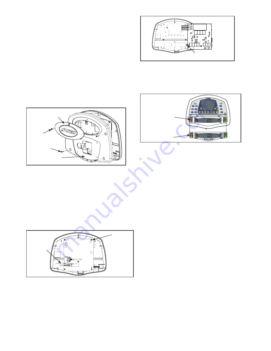
A.
Unplug the grounding wire from the main
display PC board and set the back console
cover aside. See Figure 10.
Ground
Wire
Screws
(5)
Figure 10
B.
Using a Phillips screwdriver, remove the five
screws securing the main display PC board
to the front console cover. See Figure 10.
C.
Unplug the bottom membrane ribbon cable
from the the main display PC board. See
Figure
11.
D.
Using a utility knife, pry off bottom membrane
from the front console cover. See Figure 12.
Figure 11
Ribbon Cable
E.
Peel off backing from new A/V membrane
and place on the front console cover.
See Figure 12.
F.
Plug the A/V membrane ribbon cable into
the main display PC board. See Figure 11.
G.
Using a Phillips screwdriver, reattach the
five screws securing the main display PC
board to the front console cover. See
Figure 10.
H.
Plug the grounding wire to the main display
PC board that was unplugged in step 8A.
See Figure 10.
9. Install audio cable, bracket, clamp and
adapter to front cover.
A.
Using a Phillips screwdriver, attach the two
screws (I) securing the headphone jack
mount bracket (E). See Figure 13.
B.
Attach the audio cable (B) to the headphone
jack mount bracket (E) securing it with the
flat washer and nut (attached to cable). See
Figure 13.
C.
Attach the adapter (H) securing it in place
with the headphone adapter clamp (D) and
two screws (J). See Figure 13.
Figure 12
Bottom
Membrane
A/V
Membrane
Summary of Contents for Arc Trainer 630A
Page 2: ......
Page 4: ......
Page 6: ......
Page 8: ......
Page 16: ...Service Page 4 18 This page intentionally left blank ...
Page 18: ...This page intentionally left blank ...
Page 20: ...This page intentionally left blank ...
Page 22: ...This page intentionally left blank ...
Page 42: ...This page intentionally left blank ...
Page 48: ...This page intentionally left blank ...
Page 50: ...This page intentionally left blank ...
Page 52: ...This page intentionally left blank ...
Page 54: ...This page intentionally left blank ...
Page 68: ...Service Page 4 16 ...
Page 69: ......


