APPENDIX A - ACCESSORIES AND SPARE PARTS
TPTCM
6
A-
1
1
A
B
A
B
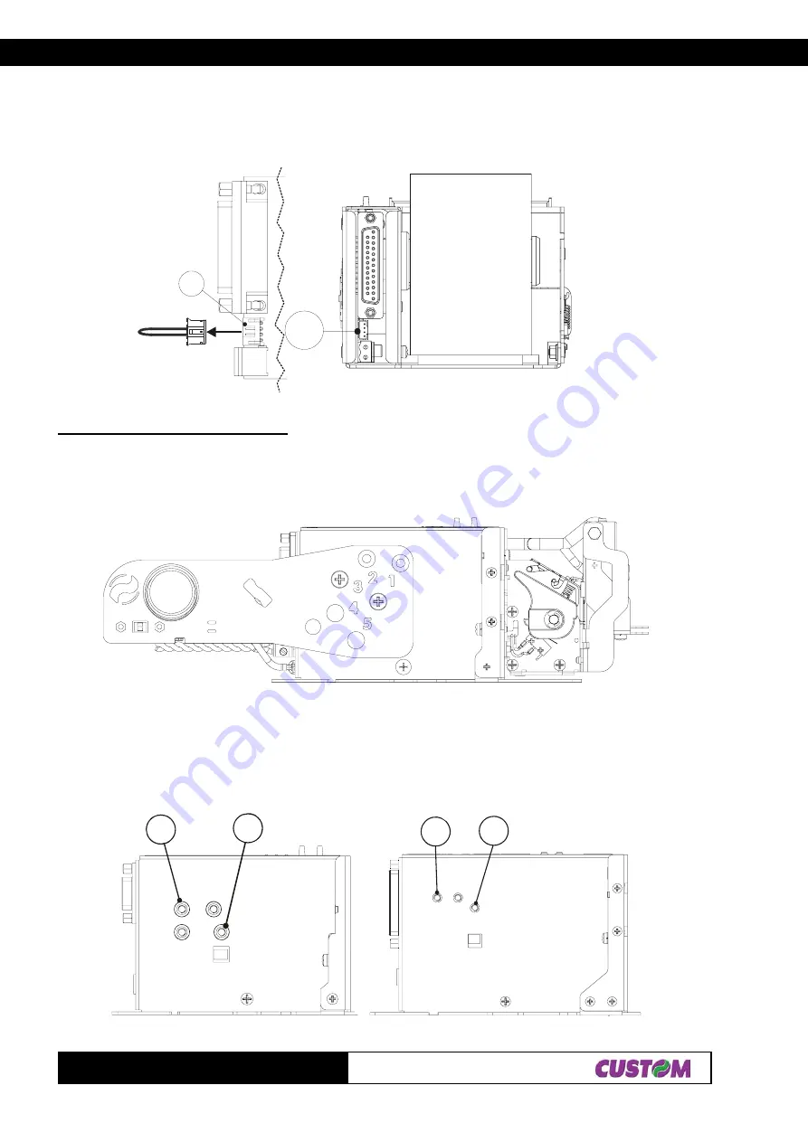
(Fig.A.10)
3. Once the roll holder support has been attached, remove the plug (1) located on the Paper Low sensor
connector on the back of the printer as shown in fig. A.9. Then insert the connector attached to the support into
the same position, it has to be verified that PINS 1-2 and 4 are connected on the connector side. If not, turn the
cabling that came on the support side.
Support adjustment and positioning
The roll holder support does not have a fixed position and may be adjusted to one of 5 different positions
corresponding to the numbers inscribed near the five holes on the support. Figure A.10 illustrates the fastening
of the support in its horizontal position.
The points at which the support is fastened to the printer frame are always the same. Figs. A.11 and A.12 show
the fastening points on the TPTCM60x and TPTCM112x printers; in the position labelled with the letter A, place
the screw that acts as pivot, and in the other position, marked B, place the one that fastens the support.
(Fig.A.9)
(Fig.A.11)
(Fig.A.12)
TPTCM60x
TPTCM112x
Summary of Contents for TPTCM
Page 1: ...TPTCM Kiosk and ticket printer TPTCM 60 mm 112 mm User Manual www custom it ...
Page 8: ...TPTCM Blank page ...
Page 10: ...TABLE OF CONTENTS TPTCM ii Blank page ...
Page 14: ...INTRODUCTION TPTCM 4 Blank page ...
Page 20: ...1 INSTALLATION AND USE TPTCM 6 1 Fig 1 7 ...
Page 110: ...4 TECHNICAL SPECIFICATIONS TPTCM 12 4 Blank page ...
Page 114: ...5 CHARACTER SETS TPTCM 4 5 Blank page ...
Page 122: ...APPENDIX A ACCESSORIES AND SPARE PARTS TPTCM 8 A Blank page ...
Page 123: ...APPENDIX A ACCESSORIES AND SPARE PARTS TPTCM 9 A Blank page ...
Page 124: ...APPENDIX A ACCESSORIES AND SPARE PARTS TPTCM 10 A Blank page ...


