1
1
8
8
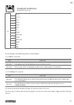
ETHERNET INTERFACE
Female RJ45 connector
J4
1 TX+1
2 +3.3 V
3 TX-1
4 RX+1
5 RX-C
6 RX-1
7 n.c.
8 GND
9 LED-LNK
10 GND
11 LED-LAN
12 GND
13 SH1
14 SH2
The functionality of two LEDs are speciied in following tables:
- For 10Base-T connection:
LED
FUNCTION
LED-LNK
Link (yellow color): the LED lights up when a connection is active
LED-LAN
Rx/Tx: (green color): the LED lights up when occurs a data reception or transmission
- For 10/100Base-TX connection:
LED
FUNCTION
LED-LNK
The LED light (yellow color) on when a connection is active and lashes when occurs a data recep
-
tion or transmission
LED-LAN
The LED light (green color) on when occurs a 100 Mbit connection and off when occurs a
10 Mbit connection
The device automatically recognizes the type of connection (cross or pin-to-pin).
The pinout shown in table represents the input signals to component J4 before the isolation voltage transformer (through-
hole pin).
23
Summary of Contents for P3
Page 1: ...USER MANUAL P3 ...
Page 2: ......
Page 4: ......
Page 6: ......
Page 10: ...10 ...
Page 18: ...18 ...
Page 26: ...26 ...
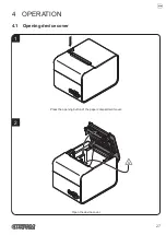
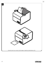
Page 30: ...Close the device cover and wait until the paper is loaded and automatically cut off 3 30 ...
Page 40: ...40 ...
Page 50: ...50 ...
Page 60: ...60 ...
Page 62: ...62 ...
Page 64: ...64 ...
Page 66: ...66 ...
Page 67: ......

