16
7. Cleaning and Inspection
7.1 Cleaning
Blast Cleaning
2600 Series body, bonnet and cap castings can be sand or bead blasted. When
blast cleaning, exercise caution to protect internal and machined surfaces to
avoid causing damage. Protect the nameplate prior to blast cleaning. It is not
recommended to blast internal parts.
Brush Cleaning
Internal parts (except for guiding surfaces) and the inside of the body and
bonnet castings can be cleaned with a wire brush and/or grinder until they are
clean. Exercise caution when brush cleaning to avoid damaging or eroding the
parts. Only clean stainless steel brushes should
be used on stainless steel components.
Immersion/Washing
Castings and internal parts should be
thoroughly cleaned with an appropriate
solvent or cleaning solution. After immer-
sion/washing, ensure that any residue is
removed and parts are dried completely.
Polishing
Guiding surfaces on the stem, stem retainer and
guide can be polished using a fine emery cloth.
7.2 Inspection
Check all valve parts for wear and corrosion.
Inspection of valve components is important to
ensure proper valve performance.
Damaged
valve parts must be repaired or replaced
with OEM parts.
The valve seat (nozzle and disc) must be
examined to determine if they have been
damaged. Typically, lapping the nozzle and/or
disc is all that is needed to restore these parts to
their original condition. Prior to lapping, or If
machining is necessary, consult section 8 and
Appendix E, Critical Dimensions.
The valve spring should be inspected for evidence of cracking, pitting, corrosion
or deformation. If any of these are found, the spring should be replaced.
The guiding surfaces on the sleeve guide and stem retainer should be
checked for evidence of pitting, corrosion, distortion or galling. If found,
these parts should be replaced.
Stems should be inspected as follows:
1. Check the bearing point on the stem tip for a smooth surface. Lap if
necessary against the mating part to improve the surface. If the
spherical contact is destroyed, the stem should be replaced.
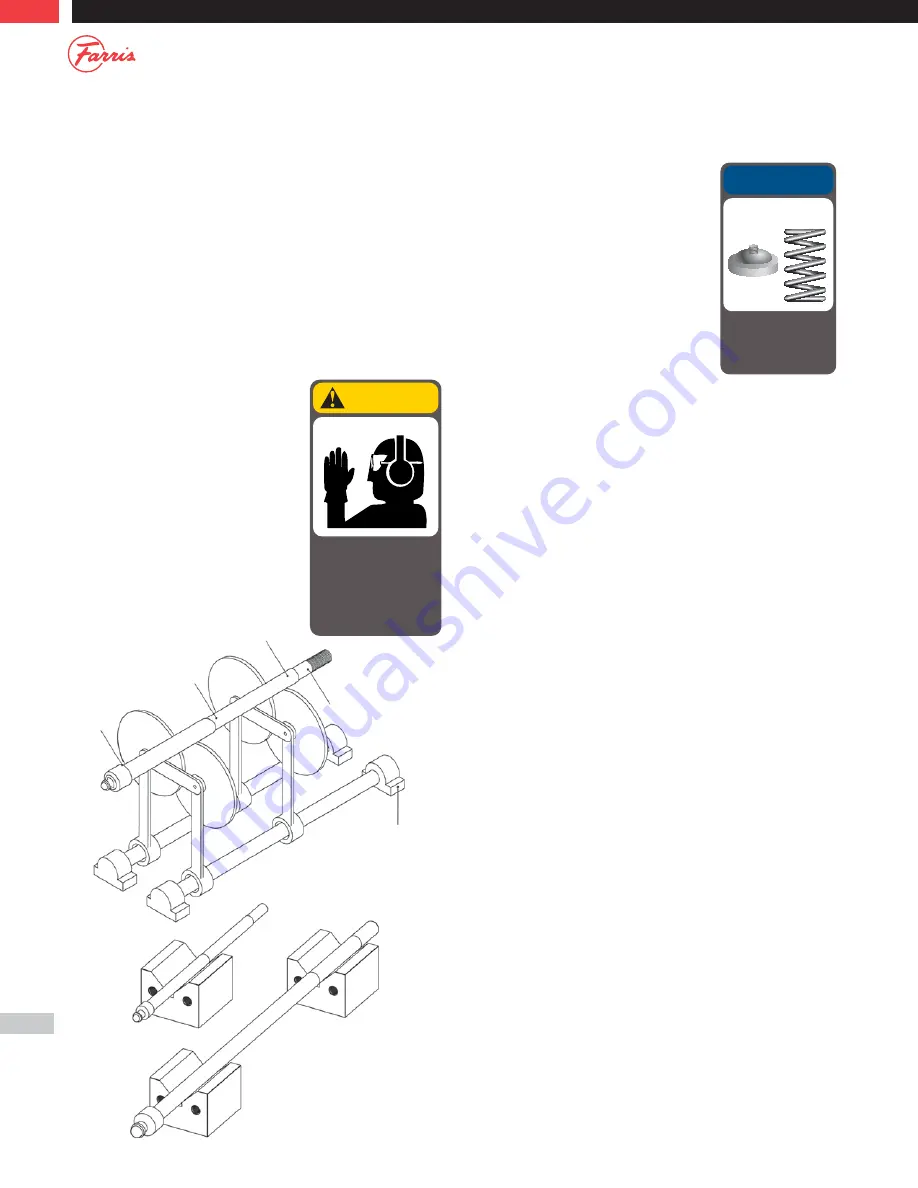
2. Check the critical stem areas for concentricity using the following
procedures (Figure 7.1 and 7.2):
a. Using “V”-Blocks or bench rollers, check the stem at the midpoint
and also at the lower spring button radius for any runout.
b. By applying a machinist’s dial indicator and rotating the stem,
the total indicator reading should not exceed 0.007 inches.
Straighten if necessary.
3. The top area of the stem just below the threads serves as the valve’s
upper guiding surface in conjunction with the spring adjusting screw.
This area is supplied from the factory with a 63 AARH finish. This area
should be free from any signs of galling, corrosion, distortion or pitting.
If seen, the stem should be replaced.
For BalanSeal valves, the bellows should be inspected for evidence of
cracking, pitting, corrosion or deformation that might develop into a leak.
Check and inspect all gaskets for evidence of damage or corrosion.
Typically, gaskets should be replaced prior to assembly.
Figure 7.2
Figure 7.1
Bench Rollers
Stem
Place Dial
Indicator
Here
Spring
Button
Seat
A
When using cleaning solvents,
take precautions to protect
yourself from potential danger
from breathing fumes,
chemical burns, or explosion.
Dispose of the waste
according to applicable
rules and regulations.
CAUTION
OEM parts only!
NOTICE
Failure to use Farris OEM
parts can create dangerous
operating conditions, poor
valve performance and will
void the warranty.
Summary of Contents for 2600 Series
Page 1: ...0713T R0 Series 2600 Maintenance Manual ...
Page 47: ...47 Notes ...


