M1277-0
ENGLISH
11
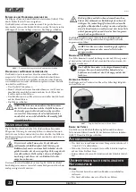
Pic.4 –
Inlet and outlet of the air flow
To achieve maximum efficiency the following conditions must
be met:
• Make sure that in the room where the dehumidifier is in-
stalled the conditions never exceed the working limits of the
machine (Tab.A);
• The room where the dehumidifier is installed must be closed;
• It is advisable to place the dehumidifier in the coldest point of
the room, where normally the humidity level is higher, pos-
sibly near the power socket.
E
WARNING: This dehumidifier is NOT suitable for
environments like laundry, or similar, where splash-
ing or dripping can penetrate water inside through the
upper air grid.
c
ontroL
paneL
Pic.5 –
The control panel
S1 - Green light ON:
The green light indicates when the dehu-
midifier is operative, otherwise it blinks on status 0 (powered but
off).
S2 - Red light, full tank:
The light blinks, together with the
green one S1, when the tank is full, missing or incorrectly posi-
tioned.
S3 - Yellow light, defrost:
The light switches on during the auto-
matic defrosting cycle.
T1 - Decrease button:
Pushing this button will decrease the
value of the display D down to 0.
T2 - Increase button:
Pushing this button will increase the value
of the display D up to C.
D - Display:
The display shows the working state of the dehu-
midifier according to the table below (Tab.B). The value 0 means
OFF, from 1 to 9 means automatic functioning and is controlled
by the humidistat that switches the dehumidifier on or off if the
value of the relative humidity is higher or lower than the one
shown in Tab.B. The value C means ALWAYS ON and the dehu-
midifier works independently from the humidity value: never-
theless, any alarm has priority over the functioning mode.
Set
Functioning
Set
Functioning
0
OFF
6
60% R.H.
1
90% R.H.
7
52% R.H.
2
86% R.H.
8
46% R.H.
3
78% R.H.
9
40% R.H.
4
72% R.H.
C
ALWAYS ON
5
65% R.H.
Tab.B –
Functioning modes
F
ailureS
The display is used by the electronic device to show particular
situations (Tab.C). If an error message is displayed please contact
your dealer for repair.
Display
Description
n
Temperature probe must be checked
u
Humidity probe must be checked
Tab.C –
Error messages
h
ow
to
use
S
tart
-
up
When the plug is connected the display D blinks for 5 seconds
and shows the last functioning mode selected: then, if the func-
tioning mode is different to zero, the display stops blinking.
S
hutdown
To switch off the dehumidifier push button T1 until the value
displayed is 0. When zero is selected both the green light S1 and
the display D blink.
t
he
deFroStinG
CyCle
The electronic board automatically performs the defrosting
cycle to melt the ice and keep the air flow efficient even at lower
temperatures. The yellow light S3 switches on when the defrost-
ing cycle is started.
h
ow
to
empty
the
tank
Open the front door and take out the tank as shown in Pic.6. Use
the front door (L) to empty the water.
Then put the tank back into its place so that the lower feet are
positioned inside the two holes (S). Then close the front door.
Pic.6 –
Holes for correct positioning of the tank
C
ontinuouS
drainaGe
The tank is prepared for continuous drainage. Installation is
very simple and, once done, you will not need to empty the tank
manually anymore. To install the continuous drainage follow
these instructions:
• Remove the rubber stopper (T).
• Connect a rubber hose with an internal diameter of 10 mil-
Summary of Contents for Nader midi 3 DL
Page 2: ...M1277 0 2 ...
Page 3: ...M1277 0 3 ...


