46
0306 / 13 013 497A
Important
Maintenance operations should be
performed at least once a year by a
technician.
•
Cut off power at multipole switch.
•
Check that there is no current.
•
Close fuel intake.
•
Check for any possible leaks.
Do not use pressurized fluid or
chlorinated products.
Setting values are found in the “
Start
up
” section.
Only used spare parts from
manufacturers.
•
Remove burner cover.
Maintenance
Removing the blast-tube.
This operation requires :
–
either the opening of the burner
body and the boiler door,
–
or removal of the burner.
1) Access via boiler door:
Proceed as indicated at the start of
the previous paragraph, up to
Q
“Withdraw the combustion
components”. Then…
•
Open the boiler door.
•
Unscrew the three blast-tube screws
from the inside.
•
Change blast-tube.
•
If necessary, fill space between the
quarl and blast-tube with refractory
material.
m
Do not block pressure take-off
pF
.
•
Close the boiler door.
•
Re-assemble.
2) Removing burner:
Proceed as indicated at the start of
the previous paragraph, up to
Q
“Withdraw the combustion
components”. Then…
•
Remove hoses, burner body, gas
manifold and combustion head.
•
Unscrew the three blast-tube screws
from the inside.
•
Change blast-tube and front seal.
•
Re-assemble.
Cleaning air circuit
•
Disconnect motor.
•
Remove all seven motor plate
screws, starting from the bottom.
•
Dislodge plate and remove unit.
•
Clean air circuit: fan and air box.
•
Reassemble unit.
Cleaning cell
•
Remove cell from its seating.
•
Clean with clean, dry rag.
•
Re-fit.
Cleaning the fuel oil pump filter
Filter is located inside pump. It must be
cleaned or replace during each
maintenance operation.
•
Close
FUEL OIL
valve.
•
Place a container under pump to
receive fuel oil.
•
Remove screws and cover.
•
Remove filter, clean or replace it.
•
Reinstall filter and cover with a new
seal.
•
Screw tightly.
•
Open
FUEL OIL
valve.
•
Check pressure and for any possible
leaks.
Motor-driven pump unit
•
Check the following :
–
atomization pressure,
–
absence of leaks in systems,
–
coupling between pump and
motor,
–
state of hose.
Checking gas filter
The external or valve filter
(integrated or pocket) must be
examined at least once a year and
filter element changed if filthy.
•
Remove cover screws.
•
Remove filter element. Make
sure no dirt is left in its cover.
•
Install a new, similar element.
•
Replace seal, cover and screws.
•
Open ball valve.
•
Check tightness.
•
Check combustion.
Leakage controller
•
Remove leakage controller.
•
Check or replace filter elements
located on
pe
and
pa.
•
Reassemble unit.
•
Check working order and for any
possible leaks.
Gas and fuel oil valves
These valves do not require any
special maintenance.
The valves must not be repaired.
Defective valves must be replaced
by a qualified specialist, who will
then carry out new check-up for
leaks, correct running and
combustion.
Checking connections
On electrical plate, fan motor, motor
pump and servomotor.
•
Check that wiring is fully tight to
all terminals.
Cleaning cover
•
Clean cover with a water and
detergent mixture.
•
Place cover back on.
Note
After each maintenance operation :
•
Check gas and fuel oil
combustion under actual working
conditions (doors closed, cover
in place, etc.) and check all
circuits for possible leaks.
•
Perform safety check-up.
•
Record results in the relevant
documents.
Checking the combustion
components
•
Remove gas manifold electrical
points, if required.
•
Remove safety screw
D
.
•
Remove mobile spindle
E
.
•
Open burner body.
•
Disconnect both ignition cables.
•
Remove hose on hydraulic
distributor.
•
Loosen by two turns all four screws
1
of
RTC
plate
m
Do not touch either screws 2.
•
Loosen nut and side screw
C
retaining gas and fuel oil feed line.
•
Take out combustion components.
Q
•
Clean entire unit.
•
Check state and settings of the
following :
turbulator, ignition electrodes,
diffusers, ignition cables and
nozzles.
•
Replace any faulty parts.
•
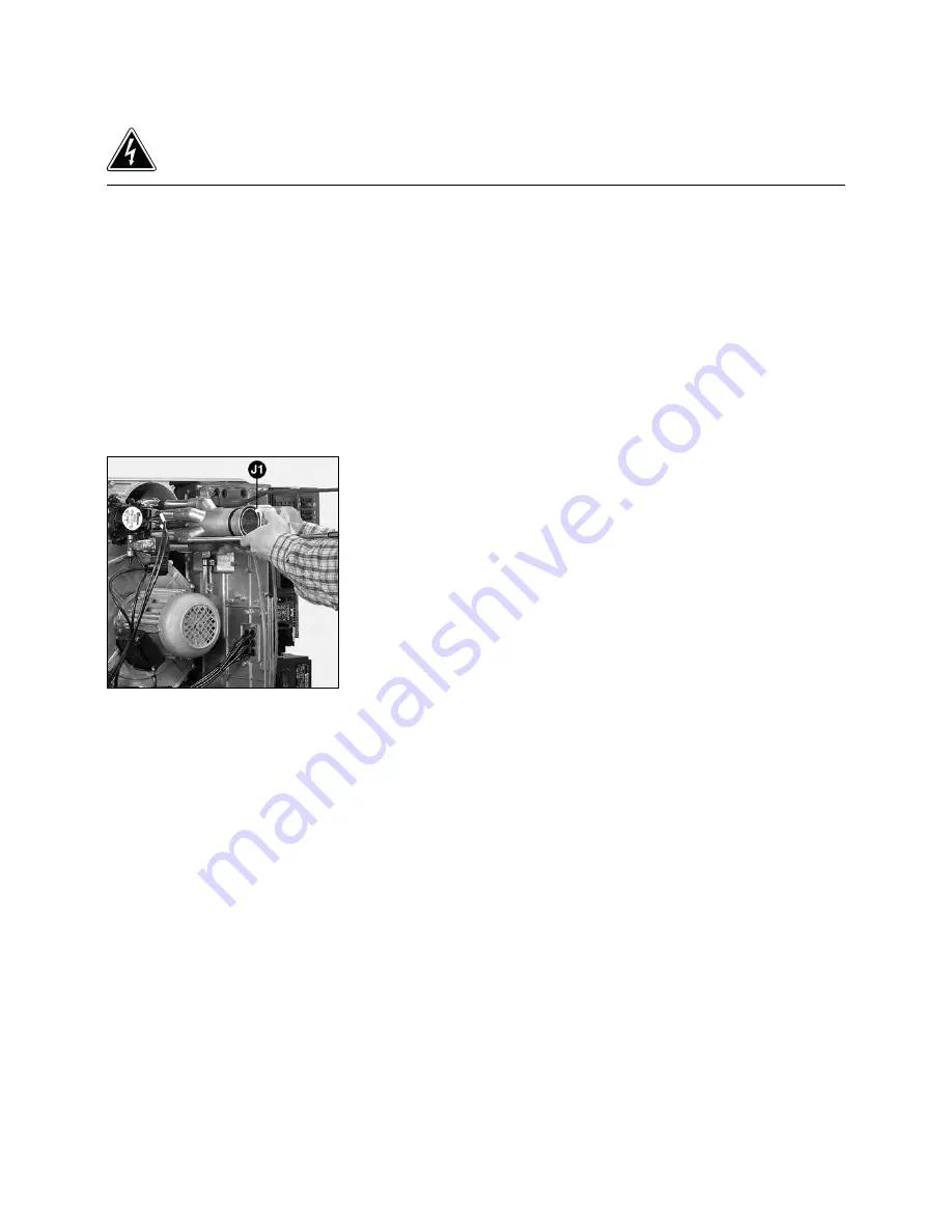
Check that O-ring
J1
is in correct
position on gas feed ligne.
•
Ensure that screw and nut
C
, hose
screw and all four screws
1
of
RTC
plate are fully tight.
Summary of Contents for C 100 B 517
Page 15: ...15 0306 13 013 497A ES Note...
Page 25: ...25 0306 13 013 497A Note ES...
Page 39: ...39 0306 13 013 497A EN Notes...
Page 49: ...49 0306 13 013 497A EN Notes...
Page 50: ...50 0306 13 013 497A...
Page 51: ...51 0306 13 013 497A...


