M039213CB Rel. 1.0 07/2010
BURNERS - BRUCIATORI - BRULERS - BRENNER - QUEMADORES -
ГОРЕЛКИ
Progressive
and fully-modulating
gas - light oil burners
MANUAL OF INSTALLATION - USE - MAINTENANCE
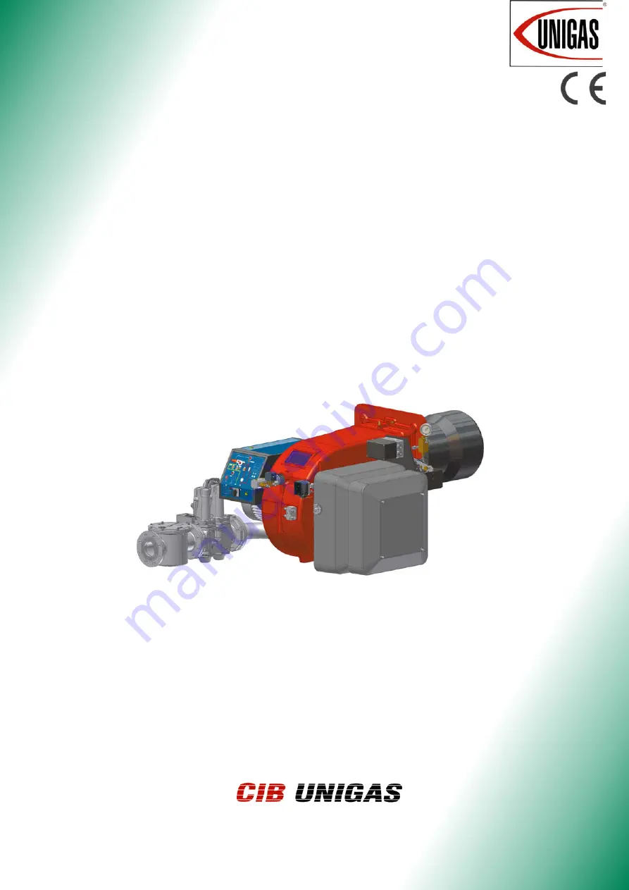
HR91A - HR92A
HR93A
HR512A - HR515AHR520A - HR525A
Page 1: ...3CB Rel 1 0 07 2010 BURNERS BRUCIATORI BRULERS BRENNER QUEMADORES Progressive and fully modulating gas light oil burners MANUAL OF INSTALLATION USE MAINTENANCE HR91A HR92A HR93A HR512A HR515A HR520A H...
Page 2: ...the flow rate 24 Measuring the gas pressure in the combustion head 24 Pressure in combustion head gas rate curves 25 Adjustments 26 Gas Filter 26 VPS504 Gas proving system 26 Adjustments brief descrip...
Page 3: ...electricity gas oil or other fuel Observe caution with hot burner components These are usually near to the flame and the fuel pre heating system they become hot during the unit operation and will rem...
Page 4: ...or explosive mixtures DIRECTIVES AND STANDARDS Gas burners European directives Directive 2009 142 EC Gas Appliances Directive 2006 95 EC on low voltage Directive 2004 108 EC on electromagnetic compat...
Page 5: ...the mixture between fuel and air takes place and consequently the flame In the burners the mixture bertween fuel and air to perform clean and efficient combustion is activated by atomisation of oil in...
Page 6: ...ng to the installed gas train DN65 in the example From the interception point draw an horizontal line as far as matching on the y axis the value of pressure necessary to get the requested fur nace inp...
Page 7: ...R525A xx Output min max kW 600 4500 770 5200 1000 6400 2000 6700 2000 8000 Fuel Natural gas Light oil Category see next paragraph Gas rate min max Stm3 h 63 476 81 550 106 677 212 709 212 847 Pressure...
Page 8: ...B UNIGAS M039213CB 8 Country and usefulness gas categories GAS CATEGORY COUNTRY I2H AT ES GR SE FI IE HU IS NO CZ DK GB IT PT CY EE LV SI MT SK BG LT RO TR CH I2E LU PL I2E R B BE I2L NL I2ELL DE I2Er...
Page 9: ...2 417 280 310 295 522 148 374 624 216 690 228 185 HR92A 65 1431 242 820 425 35 380 406 118 490 419 941 422 1309 875 434 269 299 288 360 505 M12 417 280 310 295 551 148 403 750 292 690 228 185 HR92A 80...
Page 10: ...50 535 875 x 322 762 328 270 HR515A 100 1600 323 209 250 35 672 639 145 530 508 1070 446 1810 1167 643 380 420 494 540 492 M14 552 390 390 792 150 642 942 x 382 762 328 270 HR520A 50 1670 323 199 254...
Page 11: ...et in order to find a compromise between the burner output and the generator specifications that is why the minimum output may be different from the Per formance curve minimum BACK PRESSURE IN COMBUST...
Page 12: ...pressure value in the combustion chamber to the value read on the y axis 0 10 20 30 40 50 60 70 80 90 100 50 100 150 200 250 300 Rp 2 50 DN65 DN80 DN100 0 20 40 60 80 100 120 140 50 100 150 200 250 3...
Page 13: ...e a hole on the closing door of the combustion chamber as described on paragraph Overall dimensions 2 place the burner to the boiler lift it up and handle it according to the procedure described on pa...
Page 14: ...tions of the boiler manufacturer In absence of these consider the fol lowing Cast iron boilers three pass flue boilers with the first pass in the rear part the blast tube must protrude no more than 10...
Page 15: ...NUAL Gas train 1 Gas train with valves group VGD 20 40 with built in gas pressure governor VPS504 gas proving system Gas train 2 Rp2 Gas train with valves group MBC 1200SE 2 valves gas filter pressure...
Page 16: ...unted according to the diagram on Fig 5 the gas proving test mus be performed according to the procedure set by the laws in force ATTENTION it is recommended to mount filter and gas valves to avoid th...
Page 17: ...Connect the reference gas pipe TP in figure 8mm external size pipe supplied loose to the gas pressure nipples placed on the gas pipe downstream the gas valves gas pressure must be measured at a distan...
Page 18: ...stalled electrically connect all its elements gas valves group pressure switches gas proving system Fig 13 DUNGS MBC SE Siemens SKP actuator Performance range mbar 4 20 20 40 40 80 80 150 Spring colou...
Page 19: ...lants where gravity or ring feed systems are provided install an automatic interception device see n 4 Fig 17 Fig 14 Gravity circuit Fig 15 Ring circuit Fig 16 Suction circuit Key 1 Manual valve 2 Lig...
Page 20: ...operation is automatic it is assured by a bleed flat on the piston In one pipe operation the plug of a pressure gauge port must be loosened until the air is evacuated from the system About the use of...
Page 21: ...ssible An external filter should always be installed in the suction line upstream of the fuel unit Light oil pumps 1 Inlet G1 2 2 To the nozzle G1 2 3 Return G1 2 4 Pressure gauge port G1 4 5 Vacuum g...
Page 22: ...necting burners not fitted with printed circuit Suntec TA Suntec T Respect the basic safety rules make sure of the connection to the earthing system do not reverse the phase and neutral connections fi...
Page 23: ...he motor NOTE motors for star delta start up excluded burners are supplied for three phase 400V supply and in the case of three phase 230V supply it is necessary to modify the electrical connections i...
Page 24: ...ator 2 Pressure outlet on the combustion chamber 3 Gas pressure outlet on the butterfly valve 4 Differential pressure gauge Measuring the gas pressure in the combustion head In order to measure the pr...
Page 25: ...300 0 5 10 15 20 25 30 35 40 45 40 60 80 100 120 140 160 180 200 220 240 260 280 300 320 340 0 5 10 15 20 25 30 35 40 45 50 50 75 100 125 150 175 200 225 250 275 300 325 350 375 400 425 450 0 5 10 15...
Page 26: ...SCREWS OTHERWISE THE DEVICE WARRANTY WILL BE INVALIDATE Fig 19 Keys 1 Gas filterl 2 Gas proving system 3 Gas valves 4 Air pressure switch 5 Actuator 6 Oil governor 7 Oil Adjusting cams 8 Head adjusti...
Page 27: ...id the low flame output increasing too much or that the flues temperature gets too low to cause condensation in the chimney Adjustment procedure To change the burner setting during the testing in the...
Page 28: ...e change following the steps quoted below 8 acting on the pressure stabiliser of the valves group adjust the gas flow rate in the high flame stage as to meet the values requested by the boiler utilisa...
Page 29: ...e rate unscrew to decrease 15 Move again cam III towards the minimum to meet the next screw on the adjusting cam and repeat the previous step go on this way as to reach the desired low flame point 16...
Page 30: ...lame stage loose the RA nut and screw VRA as to get the desired air flow rate moving the rod TR towards the air damper shaft the air damper opens and consequently the air flow rate increases moving it...
Page 31: ...ing cam on the next screw adjust it and go on this way to adjust all the screws in order to set the cam foil shape accor ding to the combustion values read 16 Once the cam foil shape is defined reconn...
Page 32: ...when provided To calibrate the high pressure switch proceed as follows according to its mounting position 1 remove the pressure switch plastic cover 2 if the maximum pressure switch is mounted upstrea...
Page 33: ...iagram NOZZLE DELIVERY PRESSURE bar RETURN PRESSURE MAX bar RETURN PRESSURE MIN bar FLUIDICS WR2 25 19 20 7 recommended Tab 1 Fig 21 Atomisation angle according to the return pressure _________ Flow r...
Page 34: ...ually adjusting the oil pressure see next step 9 the nozzle supply pressure is already factory set and must not be changed Only if necessary adjust the supply pressure as fol lows see related paragrap...
Page 35: ...ation adjustments see prevoius paragraphs 5 Start the burner up by means of the thermostat series and wait unitl the pre purge phase comes to end and that burner starts up 6 the burner starts up with...
Page 36: ...sition 13 to adjust the next screw set again the actuator mode to MAN turn the adjusting cam and set the actuator to AUTO mode to lock the adjusting cam on the next screw adjust it and go on this way...
Page 37: ...zzle is feeded at constant pressure while the return line pressure is adjusted by means of the pressure governor controlled by an actuator coupled to an adjusting cam The fuel amount to be burnt is ad...
Page 38: ...typer of fuel by turning the A switch on the burner control panel CAUTION if the fuel chosen is light oil be sure the cutoff valves on the feed and return pipes are open Check the control box is not l...
Page 39: ...erating meanwhile the actuator goes to the high flame position after some seconds the two stage operation begins the burner is driven automatically to high flame or low flame according to the plant re...
Page 40: ...check its shape replacing the nozzle whenever a questio nable flame shape appears Whenever the burner is used intensely we recommend preventively replacing the nozzle at the start of each heating sea...
Page 41: ...cables and the light oil flexible hoses 3 Loosen the screws V holding the gas manifold G loosen the two connectors E and remove the assembly as shown 4 Clean the combustion head by means of a vacuum...
Page 42: ...ve the photocell from its slot see next figure 4 clean the bulbe if dirty taking care not to touch it with bare hands 5 if necessary replace the bulb 6 replace the photocell into its slot Checking the...
Page 43: ...OL DEV REPEATS THE CYCLE WITHOUT GIVE CONSENT MAIN SWITCH OPEN ABSENCE OF GAS MINIMUM GAS PRESSURE SWITCH FAULT OR BAD SETTING BOILER THERMOSTATS OPEN OVERLOAD TRIPPED INTERVENTION FUSES INTERVENTION...
Page 44: ...FOIL 16 4 1 GAS PRESSURE 10 18 16 4 2 GAS VALVE HOUSING 10 19 BRACKET 16 4 3 SKP ACTUATOR 10 27 AIR ADJUSTING CAM REGULATING NUT 16 4 4 SKP ACTUATOR 10 29 ACTUATOR 16 4 5 GAS PROVING SYSTEM 11 STANDAR...
Page 45: ...C I B UNIGAS M039213CB 45...
Page 46: ...0174 GAS VALVE ACTUATOR SKP15 2190181 2190181 2190181 GAS VALVE ACTUATOR SKP25 2190183 2190183 2190183 GAS VALVE GROUP Rp2 Dungs MBC1200SE 21903M5 21903M5 21903M5 GAS VALVE GROUP DN65 Dungs MBC1900SE...
Page 47: ...1 2190181 GAS VALVE ACTUATOR SKP25 2190183 2190183 2190183 2190183 GAS VALVE GROUP Rp2 Dungs MBC1200SE 21903M5 21903M5 21903M5 21903M5 GAS VALVE GROUP DN65 Dungs MBC1900SE 21903M6 21903M6 21903M6 2190...
Page 48: ...the burner a proper hearthing Please see the attached wiring diagram Burners not fitted with printed circuit WIRING DIAGRAM SE05 680 Progressive burners WIRING DIAGRAM SE05 681 Fully modulating burner...
Page 49: ...n terminals 6 and 8 otherwise the mechanism will not start up the burner For a burner to start up the following conditions must be met Mechanism not blocked reset Damper closed Limit contact switchZ m...
Page 50: ...tection IP40 Permitted ambient temp 20 60 C Min temperature trans storage 50 C Weight apparatus approx 1 000g base approx 165g Ionisation monitor voltage in detector electrode normal working 330V 10 t...
Page 51: ...for creating current between terminals 17 and 19 t5 interval for creating current between terminals 19 and 20 t6 post ventilation time t7 interval between startup consent and current created at termin...
Page 52: ...and data subject to change Errors and omissions exceptd C I B UNIGAS S p A Via L Galvani 9 35011 Campodarsego PD ITALY Tel 39 049 9200944 Fax 39 049 9200945 9201269 web site www cibunigas it e mail ci...