background image


Cubix Corporation 

 2800 Lockheed Way 

 Carson City, NV 89706-0719 

 Page 9 

Sales 800.829.0550 


http://www.cubix.com


 [email protected] 

 xpander-rackmount2-g3 20181115 

10. Replace the Xpander top cover and screws. 
11. Gently slide Xpander back in place. 
12. Secure Xpander into place within the cabinet using the front-panel screws provided. Use the 

Philips #2 screwdriver. 

13. Connect the PCIe x16 external cable to the HIC in the host computer. 
14. Connect power to Xpander. 


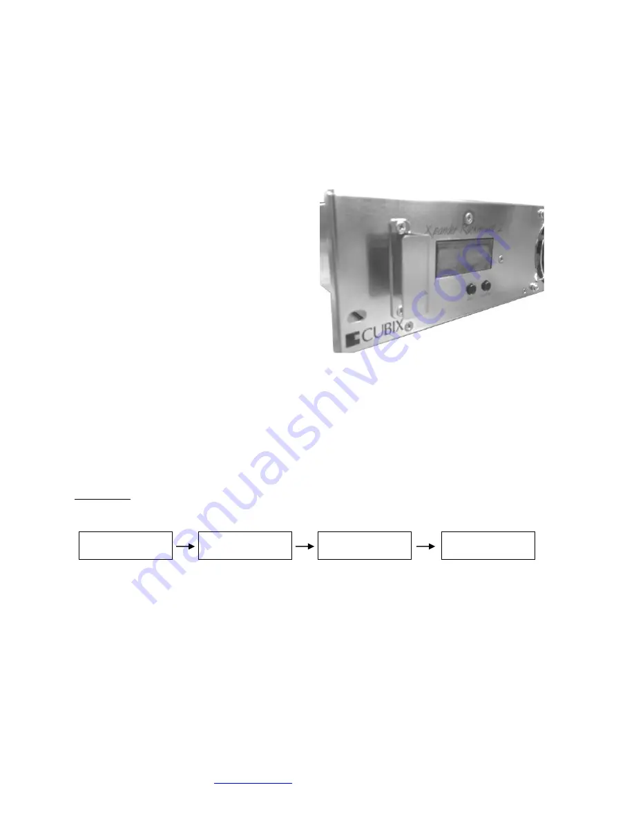
Front Panel LCD 

Xpander Rackmount 2 front panel LCD 
provides enclosure details and status. 
Beneath the LCD are two buttons: left button 
scrolls through main-menu and right button 
scrolls through sub-menu. 
 
When you first connect power, Xpander 
comes up in standby mode. The LCD displays 
Cubix on the top line and Corporation on the 
bottom line. This is the Start menu. Access all 
other main menu items by pressing the left 
button. 
 
The upper right corner of the LCD shows a flashing asterisk *. This indicates that the on-board 
Micro-Controller Unit (MCU) is running properly. If the asterisk is not flashing or the LCD is not 
responding, reset the MCU by pressing and holding the left button for 3 seconds. A 
corresponding HB (heartbeat) LED on the main board also shows the MCU is working. 
 
When a fault occurs, the LCD will jump to that fault and the LCD backlight will flash on / off. 
Press the left button to acknowledge the fault and the LCD will stop flashing and enable normal 
operation. The LCD will continue to display the fault at the applicable sub-menu until you clear 
the fault. 
 
Start Menu 


Menu 

Sub-menu 

Sub-menu 

Sub-menu 


Main menu:  Cubix Corporation 
Sub-menu:   PCB Assembly 


Board Number 


EEPROM Revision 


Board Revision 

Sub-menu:   MCU (Micro-Controller Unit) Firmware 


Release Number 


Release Date 

Sub-menu:   Cubix Serial Number 


Cubix 

Corporation 

Cubix 

A09150 Rev 0B 0A 

MCU Firmware 

Rel 01 04-28-14 

Serial Number 

10200001 

Summary of Contents for Xpander RackMount 2

Page 1: ...heoretical transfer rate of 8 0Gbs x16 128Gbps Xpander Rack Mount 2 Gen 3 Technical Specifications Expansion slots x16 std PCI Express Gen 3 0 x16 mechanical electrical Number of slots 2 slots in one mainboard Form factor support 2 double wide full length full height accelerators Connecting cable External PCI Express x16 136 pin cable Cable connector x16 136 pin Length standard 2 00meters 78 74inc...

Page 2: ...stallation requires no driver or other software The only drivers you install are those for the devices you install Cubix provides a standard two year warranty with the purchase of each Rack Mount 2 Optional The standard external PCIe cable length is 2meter Optional 1m PCIe cable is also available The maximum duty cycle for PCIe cables is 250 mating cycles Cubix offers a third year warranty option ...

Page 3: ...You will feel the cable connector click into place See the image of a properly seated connector at the right 6 Connect a power cord to the receptacle at the Xpander enclosure rear 7 Power on the host computer Xpander also powers on If you have properly seated the HIC in the host PCIe slot you will see the 8 LEDs at the top edge of the HIC light steady green 8 Check the mainboard Cable P0 LED which...

Page 4: ...re spinning Xpander is functioning properly once the Cable LED P0 lights green Proceed to install adapters 9 Switch off AC power to the host computer Leave the power cord and the external PCIe cable to the host computer connected 10 Switch off power and remove the power cord from Xpander Warning Before installing or removing cards in Xpander switch off AC power and wait for the mainboard 5V Standb...

Page 5: ... 11 Remove the two screws holding the end bracket retaining panel from Xpander rear and remove the retaining panel See the image below 12 Install the accelerators in the appropriate riser slots Make sure the baffle plate remains in place The baffle plate is required for passively cooled accelerators like NVIDIA or AMD GPUs or Intel Xeon Phi coprocessors ...

Page 6: ...n Step 19 17 Install the single wide cards at the far right facing the rear of Xpander 18 Power up the host computer and Xpander to confirm that the appropriate Xpander slot link LEDs are lit green which confirms that you have installed the controller s correctly in each slot 19 Confirm that your operating system OS has detected the new controller s In a PC running Microsoft Windows check Windows ...

Page 7: ...aging you will find four brackets that mount within the four corners of your rack mount cabinet screws nuts and G nuts for use in mounting Xpander within a cabinet See the image at the right 1 Shut down the host and Xpander normally and disconnect all data and power cables connected to Xpander 2 Find in packaging the rackmount slide rails with a bag of 8 x mounting screws taped to one of the rails...

Page 8: ...d disconnect the power cord 3 Remove the two front panel screws that secure Rack Mount 2 to the rackmount cabinet 4 Gently pull the Xpander toward you 5 Remove the screws holding in place the Xpander front top cover remove the top cover and set it aside 6 Make sure the 5V Standby LED in Xpander is off 7 Remove the screws holding each of the end brackets 8 Remove the two screws holding the end brac...

Page 9: ...er main menu items by pressing the left button The upper right corner of the LCD shows a flashing asterisk This indicates that the on board Micro Controller Unit MCU is running properly If the asterisk is not flashing or the LCD is not responding reset the MCU by pressing and holding the left button for 3 seconds A corresponding HB heartbeat LED on the main board also shows the MCU is working When...

Page 10: ...justs from 6V min 25deg C or lower at 50 to 12V max 50deg C or higher at 100 Fan voltage is the same for all fans Status PWR OFF is 0V at 00 system is in standby Status Running aaV at pp fan is good aa fan voltage and pp fan power percent Status STOPPED is 12V at 100 fan fault fan voltage is set to full on Status NO FAN aaV at pp Xpander can be configured with 1 2 3 or 4 fans No fan means fan is n...

Page 11: ...ro K6000 M6000 and P6000 Fan Profile Guidelines GPU Mode supports 4 x double wide GPUs like NVIDIA Quadro or GTX Series High Performance Mode supports 2 3 double wide GPUs and Performance Mode Performance Mode supports 2 x double wide GPUs Quiet Mode supports 1 x double wide GPU or 4 x single wide GPUs Shipping Procedure Before shipping Xpander remove any installed graphics or other controller s u...

Page 12: ...flashes it is transferring data at a reduced bandwidth because you installed the PCIe x16 HIC in a Gen 1 slot or a PCIe x8 electrical slot If your HIC is PCIe x8 you installed it in a Gen 1 slot The HIC operates at full bandwidth when installed in a PCIe Gen 2 slot Issue Slot LED inside Xpander does not light green Resolution Shut down the OS gracefully power down Xpander and reseat the GPUs in ea...

Page 13: ...ch will either stop the LCD flashing and the LCD will remain at the fault or the LCD will jump to the next fault and the LCD backlight will once again flash on off Issue The front panel LCD screen either does not respond or is blank even though Xpander is operating Resolution Press and hold the MIB Select button to reset the Micro Controller Unit MCU Issue The front panel LCD screen either does no...

Reviews: