background image

Setup

Connecting to a Computer or Network (Optional)

CubiScan 125

19

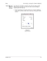
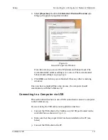
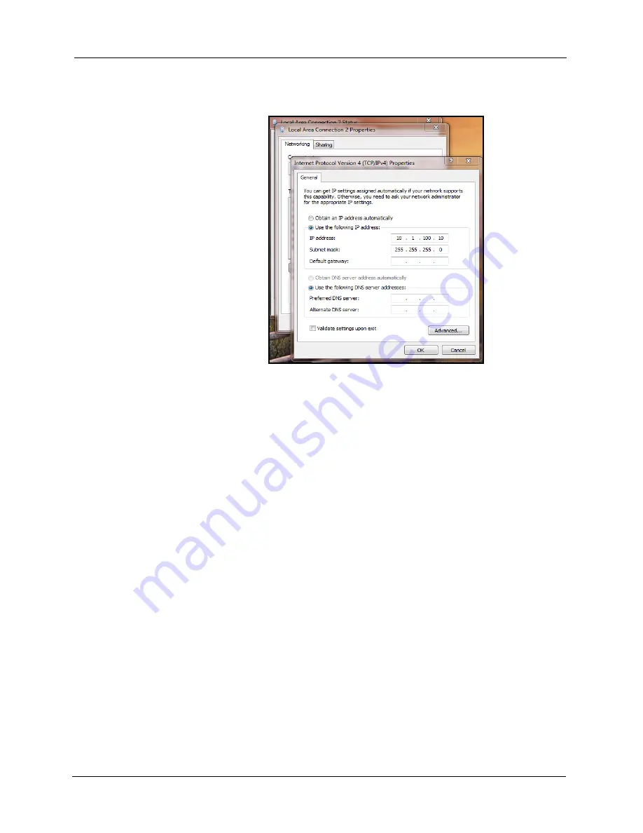
2. Select 

[Properties]

. Double-click 

Internet Protocol Version 4

 to 

bring up the general properties window.

From this screen you can set the IP address and Subnet mask. The 
recommended IP address setting is 10.1.100.10. The recommended 
Subnet mask setting is 255.255.255.0.

3. Click 

[OK]

 to exit when you are finished. Close any other remaining 

windows.

Once you have completed this setup process, the computer should 
communicate with the CubiScan 125.

Connecting to a Computer via USB

This section describes how to use a USB connection to connect a computer 
to the CubiScan 125.

If you are using the USB cable (not supplied) connection:

1. Connect the USB cable to the CubiScan 125’s USB port located on the 

controller box, as shown in 

Figure 13

2. Make sure that the proper driver has been installed on the PC (see 

below).

3. Connect the USB cable to the PC.

Figure 19

General Properties Window

Summary of Contents for 125

Page 1: ...Operations and Technical Manual Version 1 3 Quantronix Inc Cubing and Weighing Systems 380 South 200 West P O Box 929 Farmington Utah 84025 U S A Phone 1 801 451 7000 Fax 1 801 451 0502 Website http www cubiscan com ...

Page 2: ...n patents CubiScan 110 measurement products are protected by one or more of U S Patent Re42 430 and foreign patents CubiScan 125 measurement products are the subject of U S Patent 8 928 896 Another U S patent is pending CubiScan 225 measurement products are protected by one or more U S patents refer to U S Patent 9435637 This document and website Copyright 2017 by Quantronix Inc All rights reserve...

Page 3: ...ly equivalent to the original product or part or iii refund the purchase price of the product after Buyer has returned the product to Seller For purposes of this warranty agreement Buyer shall mean and refer to i the party which originally whether from Seller directly or from an authorized distributor agent or reseller who is authorized by Seller purchases or leases under a written equipment lease...

Page 4: ...ted into used alongside of or in conjunction with a product manufactured by Seller TO THE EXTENT PERMITTED BY LAW THIS WARRANTY AND THE REMEDIES SET FORTH ABOVE ARE EXCLUSIVE AND IN LIEU OF ALL OTHER WARRANTIES REMEDIES AND CONDITIONS WHETHER ORAL OR WRITTEN STATUTORY EXPRESS OR IMPLIED TO THE MAXIMUM EXTENT ALLOWED BY LAW SELLER SPECIFICALLY DISCLAIMS ANY AND ALL STATUTORY OR IMPLIED WARRANTIES I...

Page 5: ... log see Appendix B Firmware Log on page 86 Deleted the Communications Protocol and made it a separate document This document was created with the purpose of providing the most accurate and complete information If you have comments or suggestions for improving this manual contact Quantronix at manual cubiscan com Manual updated July 12 2017 ...

Page 6: ... Connecting to a Computer or Network Optional 15 Connecting to a Computer via Ethernet 16 Connecting to a Computer via USB 19 Connecting to a Computer via Serial RS 232 C 21 Installing Qbit Optional 21 Setup Checklist 21 Chapter 3 Operation 23 Before You Begin 23 CubiScan 125 Touchscreen 24 Touchscreen Care 24 Cubing and Weighing 25 Cubing and Weighing Using Qbit 25 Cubing and Weighing Using the T...

Page 7: ...ning the Gate Filters 59 Removing the Controller 59 Chapter 7 Troubleshooting 61 No Response When You Turn Power On 61 Scale Readings Are Not Accurate 62 Dimension Readings Are Not Accurate 62 Computer Error Messages 62 About 63 Version 63 Config Audit 65 Cal Audit 66 Diagnostics 68 Scale Diagnostics 68 Gate Diagnostics 69 Touchscreen Diagnostics 74 Sensor Diagnostics 76 Testing 79 Scale 79 Gate 8...

Page 8: ...t Serial and USB Connectors 16 Figure 14 Installation Bubble 17 Figure 15 Device Installed Bubble 17 Figure 16 Installation Process Bubble 17 Figure 17 Adapter is Ready to Use 17 Figure 18 Status Window 18 Figure 19 General Properties Window 19 Figure 20 CubiScan 125 Touchscreen 24 Figure 21 Measurement Display 26 Figure 22 Package on Platform 27 Figure 23 Ultrasound Measurement Display 28 Figure ...

Page 9: ...n Screen 54 Figure 52 Second Sensor Calibration Screen 54 Figure 53 Third Sensor Calibration Screen 55 Figure 54 Fourth Sensor Calibration Screen 56 Figure 55 Fifth Sensor Calibration Screen 57 Figure 56 Sensor Calibration Complete 57 Figure 57 Control Box 60 Figure 58 Home Screen 64 Figure 59 About Version 64 Figure 60 Home Screen 65 Figure 61 About Config Audit 66 Figure 62 Home Screen 67 Figure...

Page 10: ...Figure 75 Home Screen 79 Figure 76 Test Scale 80 Figure 77 Home Screen 81 Figure 78 First Gate Test Screen 82 Figure 79 Third Gate Diagnostic Screen 82 Figure 80 Parts List 85 ...

Page 11: ...and outputs to a user supplied PC Capacity for the ultrasound sensors is 24 x 30 x 36 inches with a resolution of 0 1 inches gate sensors can measure up to 18 x 18 x 12 inches with a resolution of 0 05 inches The CubiScan 125 also includes an integrated high accuracy 50 x 0 005 lbs scale Each unit has one active serial communication port one Ethernet port and one USB port Proprietary interface sof...

Page 12: ...s CubiScan 125 2 Specifications Power Requirements 100 240 VAC 50 60 Hz Environmental Operating Temperature 32 to 104 F 0 to 40 C Humidity 0 to 90 non condensing Measuring Sensor Infrared light beam and ultrasonic Figure 1 CubiScan 125 ...

Page 13: ...98 NT 2000 Pentium II processor 20 megabytes of disk space screen resolution setting of 800 X 600 Quantronix s QBIT software can be used to interface with the CubiScan 125 Measurement Range Ultrasound Sensors Gate Sensors Length 2 0 to 24 0 in 5 0 to 60 0 cm 0 10 to 18 00 in 0 2 to 45 0 cm Width 2 0 to 30 0 in 5 0 to 80 0 cm 0 10 to 18 00 in 0 2 to 45 0 cm Height 2 0 to 36 0 in 5 0 to 90 0 cm 0 10...

Page 14: ...Description Specifications CubiScan 125 4 Display Integrated TFT LCD touchscreen displays length width height weight unit of measure 2D and height profile and diagnostic codes Outputs Serial 1 Ethernet 1 USB 1 ...

Page 15: ...Scan 125 on page 14 Connecting to a computer or network optional page 15 Installing the Qbit software optional page 21 Unpacking The CubiScan 125 is shipped in a single container with all components The glass platform is packed in a separate cardboard box inside the crate Remove the wood slats and the packing material and lift the CubiScan 125 components carefully from the crate Do not remove the ...

Page 16: ...25 on a solid stable surface for assembly see Assembling the CubiScan 125 on page 7 If any of the components or accessories are missing or defective contact Quantronix Placement The CubiScan 125 is designed to be operated in a warehouse environment however for proper operation the following conditions should be met if possible Do not subject the CubiScan 125 to extremes in temperature or humidity ...

Page 17: ...s close to the CubiScan 125 as possible The operator needs to use the keyboard or mouse on the computer while cubing and weighing packages using the CubiScan 125 Orient the CubiScan 125 so the touchscreen faces the operator Assembling the CubiScan 125 The CubiScan 125 is almost completely assembled when shipped You only need to attach the top sensor support route the height sensor cable remove the...

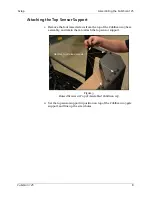
Page 18: ... raised screws from the top of the CubiScan 125 base assembly and retain them to attach the top sensor support 2 Set the top sensor support in position on top of the CubiScan 125 gate support and line up the screw holes Figure 3 Raised Screws at Top of Assembled CubiScan 125 Remove four raised screws ...

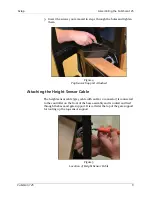
Page 19: ...nsor Cable The height sensor cable gray cable with an RJ 12 connector is connected to the controller on the front of the base assembly and is routed and tied through the base and gate support It is coiled at the top of the gate support for routing up the top sensor support Figure 4 Top Sensor Support Attached Figure 5 Location of Height Sensor Cable ...

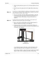
Page 20: ...r cable from the top of the gate support up the side of the top sensor support as shown below 2 Place the supplied cable ties over the sensor cable and through the holes on either side and secure them to hold the sensor cable in place Figure 6 Routing the Height Sensor Cable ...

Page 21: ... 11 3 Place the sensor cable cover over the wire as shown below aligning the screws on the side of the sensor cover with the slots in the top support Slide the sensor cover into place and tighten the screws Figure 7 Attaching the Sensor Cable Cover ...

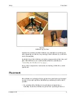
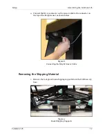
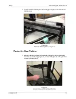
Page 22: ...onnector on the sensor cable to the connector on the top of the height sensor as shown below Removing the Shipping Material 1 Remove the four green foam shipping supports from the CubiScan 125 base Figure 8 Connecting the Height Sensor Cable Figure 9 Foam Shipping Supports ...

Page 23: ...e and remove the bubble wrap Placing the Glass Platform 1 Remove the glass cubing and weighing platform from the cardboard box that was in the shipping crate and carefully place it on the platform frame as shown below Figure 10 Cable Tie Holding Measuring Gate Figure 11 Glass Cubing and Weighing Platform ...

Page 24: ... 3 Connect the other end of the AC power cord to a standard power outlet 4 Use the power switch on the left side of the controller box shown above to turn the CubiScan 125 on and off NOTE The CubiScan 125 should be powered on before running the Qbit application to cube and weigh packages Turning On the CubiScan 125 Specific procedures must be followed each time you turn on the CubiScan 125 as foll...

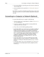
Page 25: ...g operating methods Connect the CubiScan 125 to a host system via a standard 10 100Base T Ethernet TCP IP port This is the recommended method and all parts needed to connect the CubiScan 125 to a computer via an Ethernet connection have been supplied by Quantronix You may need to load the driver To load the driver onto the computer follow the instructions on page 16 You can use Qbit software or th...

Page 26: ...ernet connection option 1 Install the driver that is needed for further information on installing the driver see below 2 Connect the Ethernet cable supplied to the CubiScan 125 s Ethernet port as shown in Figure 13 3 Attach the Ethernet cable to the TRENDnet USB to Ethernet cable adapter supplied 4 Connect the TRENDnet cable adapter to the PC NOTE The following screen images were taken from a Wind...

Page 27: ...en Wait a few moments for the installation process to finish and the following bubble will pop up If you clicked on the installation bubble the following window will open Once the driver has finished the installation process it will report that the adapter is ready to use Figure 14 Installation Bubble Figure 15 Device Installed Bubble Figure 16 Installation Process Bubble Figure 17 Adapter is Read...

Page 28: ...installed you need to set the static IP address and the Subnet mask of the adapter You can access these network settings by completing the following steps 1 Under Control Panel Network and Internet Network and Sharing Center locate and click on the correct connection to bring up the status window Figure 18 Status Window ...

Page 29: ...nished Close any other remaining windows Once you have completed this setup process the computer should communicate with the CubiScan 125 Connecting to a Computer via USB This section describes how to use a USB connection to connect a computer to the CubiScan 125 If you are using the USB cable not supplied connection 1 Connect the USB cable to the CubiScan 125 s USB port located on the controller ...

Page 30: ...cally installed A notification bubble will pop up in the bottom right corner of the screen when the installation process is finished If you are using Windows XP the driver will need to be loaded manually 2 To determine which COM port the computer has assigned to the USB port go to Control Panel Hardware and Sound 3 Click on Device Manager to display the Device Manager window 4 Click the arrow next...

Page 31: ...tation if necessary to identify the ports If the serial port is 9 pin connect the serial cable directly to the serial port If it is 25 pin use a 25 pin to 9 pin adapter not supplied 4 To secure the RS 232 serial cable tighten both screws at each end of the cable It is important that the cable be secure Installing Qbit Optional A flash drive is available containing the Qbit software program which c...

Page 32: ...able page 15 7 Has the AC power cord been connected correctly page 14 8 If you are using Qbit to operate the CubiScan 125 has the software been copied onto your computer s hard disk drive Refer to the Qbit User Guide for information 9 Does the CubiScan 125 require recalibration The CubiScan 125 was calibrated at the factory but may require recalibration due to handling during shipping Refer to pag...

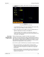
Page 33: ...stic procedures that take about 5 seconds Do not touch the CubiScan 125 platform during these 5 seconds 4 The CubiScan 125 must be zeroed each time it is turned on For instructions on zeroing the CubiScan 125 see Zeroing the CubiScan 125 on page 31 NOTE Do not lean on or touch the CubiScan 125 glass platform or the object while the object is being measured and weighed Any kind of contact with the ...

Page 34: ...25 on page 31 Tap Menu to select configuration or calibration functions Other touch keys may be used for specific functions and are described in the instructions for that function Refer to Chapter 4 Configuration on page 28 for information on configuration and to Diagnostics on page 60 for information on diagnostics Touchscreen Care Never use a sharp or hard tipped object to tap on the touchscreen...

Page 35: ...ound sensors on the CubiScan 125 frame Irregular objects are measured by the infrared sensors in the CubiScan 125 measuring gate by moving the gate over the object on the platform Refer to the appropriate following section for instructions Cubing and Weighing Using Qbit Refer to the Qbit User Guide for instructions on measuring weighing and other functions in Qbit The Qbit User Guide is provided o...

Page 36: ...efore you can place an object on the platform When you place an object on the platform the indicator goes off Ready indicator This indicates that the CubiScan 125 is ready for cubing and weighing Home indicator This indicates that the measuring gate is positioned in the home position on the right hand side Zero button Tap this key to reset the scale to zero make sure the platform is empty Refer to...

Page 37: ... t interfere with the sensors The zero indicator should be lit 2 Place the package or object to be cubed and weighed on the platform and slide it against the back corner until it is in contact with both side panels The zero indicator light will go out NOTE Do not lean on or touch the CubiScan 125 platform or the object while an object is being measured Any kind of contact with the platform during ...

Page 38: ...touchscreen The measuring gate can measure opaque objects as small as 1 inch 2 mm An image of the object is displayed on the touchscreen as it is measured When you begin measuring with the measuring gate you must start with the gate on the right side of the CubiScan 125 or home position indicated by the home indicator on the touchscreen You can then use either of the following two methods to measu...

Page 39: ...idth height and weight of the object are displayed NOTE Do not move the gate too quickly across the platform A gate speed error is displayed on the touchscreen if you move it too quickly 4 Remove the object from the platform Wait for the zero indicator to light before placing the next object on the platform 5 If the zero indicator does not light it means that the CubiScan 125 needs to be zeroed To...

Page 40: ...Operation Cubing and Weighing CubiScan 125 30 Figure 25 Measuring Gate Display Figure 26 Height Display ...

Page 41: ...an 125 to operate properly The CubiScan 125 tries to zero itself automatically However you may need to use this option in the following circumstances If during a long measuring session environmental conditions temperature and humidity have changed noticeably If you suspect that the last zeroing was in error something was on the platform NOTE Make certain that the platform is free of all objects be...

Page 42: ...bit installed you can use Qbit to set up the measurement and dimensional weight units select the CubiScan 125 communications port perform calibration and other functions Refer to the Qbit User Guide for instructions on measuring and other functions in Qbit The Qbit User Guide is provided on the flash drive with the Qbit application or you can download it from the Quantronix website at www cubiscan...

Page 43: ...tap MENU NOTE If you have set up a password previously in the system configuration you need to enter the password to unlock the menu Refer to page 36 2 Tap CONFIGURE Select the Operation option if it is not already selected Figure 27 Home Screen Figure 28 Configure Operation ...

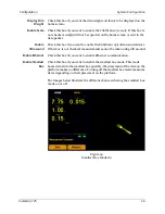
Page 44: ...e CubiScan 125 s ultrasound sensors If this box is not checked measurements cannot be taken using ultrasound Enable Ethernet Check this box if you want to enable Ethernet communication Enable Smallest Box Check this box if you want to enable the smallest box mode This mode boxes items into the smallest box possible the placement of the item on the platform makes no difference Turning off the small...

Page 45: ...you want the filter mode option available on the home screen You can then enable or disable the filter mode from the home screen In this mode the CubiScan 125 measures only the largest item that is on the platform the item that takes up the most pixels Height is not taken into account As shown below the largest item s measurements are displayed even though it is not the tallest item Items that wer...

Page 46: ...Spanish Protocol From this drop down box you can select which protocol is used The options are Standard Expanded CS 100 L and Custom The Standard option is the default and works the best with Qbit software The Expanded option includes more information in the data packet such as the packet number and date and time The CS 100 L option makes the data packet backwards compatible with the CubiScan 100 ...

Page 47: ...he compression feature is disabled When you select the Enabled option a Compression checkbox appears on the home screen Compression mode can then be enabled or disabled from the home screen When you select the Auto Off option a Compression checkbox appears on the home screen With this option selected you can measure an object in compression mode once then compression mode is automatically turned o...

Page 48: ...p Hgt mm This field displays the height of the compression plate in millimeters The default setting for this field is 085 the height of the compression plate that Quantronix can provide This value should not be changed unless you are using a different compression weight To change the tare value simply tap on the number and enter the new value Units This section discusses the options available on t...

Page 49: ...02 0 005 or 0 01 Dim Factor In this field you can select the dim factor that will be used The options are domestic and international Factors In these fields you can view or change the current dim factor values The following table displays the default dimensional weight factors used by the CubiScan Figure 34 Configure Operation 139 International inches pounds in lb 166 Domestic inches pounds in lb ...

Page 50: ...ptions available on the Ethernet menu Complete the following steps to access the Ethernet menu 1 From the home screen tap MENU NOTE If you have set up a password previously in the system configuration you need to enter the password to unlock the menu Refer to page 36 Figure 35 Home Screen ...

Page 51: ...he current IP address SubNet This is the current subnet mask GateWy This is the current gateway setting Enable Check this box to enable the in use Ethernet DHCP Check this box to enable the DHCP Static This section describes the various settings and options of the static Ethernet IP This is the static IP address SubNet This is the static subnet mask GateWy This is the static gateway setting Figure...

Page 52: ...n discusses the options available on the Other menu Complete the following steps to access the Other menu 1 From the home screen tap MENU NOTE If you have set up a password previously in the system configuration you need to enter the password to unlock the menu Refer to page 36 Figure 37 Home Screen ...

Page 53: ...tton displays all firmware files that are saved on the SD card If you would like to update the CubiScan 125 to a certain firmware file select it in the list displayed and tap Update Firmware Reset Tap this button to reboot the system after updating the firmware The system must be rebooted each time the firmware is updated Date Time This displays the current date and time Figure 38 Configure Other ...

Page 54: ...t annually If the CubiScan 125 is used heavily scale calibration should be performed monthly Perform quality checks as needed depending on how critical the accuracy of the data is to you Recalibrate if you are outside the tolerance of 0 05 inches 0 1 cm for the gate 0 010 pounds 0 005 kg for the scale or 0 1 inches 0 2 cm for the ultrasound sensors During quality checks or when calibrating make su...

Page 55: ...brating without an accurate known weight within 01 of a lb kg can make all future weight readings inaccurate Take the following steps to calibrate the CubiScan 125 scale NOTE When calibrating the scale the CubiScan 125 must be stable with no movement of the platform such as that caused by vibration or air movement 1 At the home screen tap MENU NOTE If you have set up a password previously in the s...

Page 56: ... selected Make sure the weight and units displayed are correct for the test weight you are using Tap Next to begin the scale calibration 3 The following screen is displayed Clear the scale of all objects and tap Next to continue Figure 40 First Scale Calibration Screen Figure 41 Second Scale Calibration Screen ...

Page 57: ...ts on the CubiScan 125 platform Tap Next to continue 5 You have now finished calibrating the scale Tap HOME to return to the home screen or if you would like to try calibrating the scale again tap Next Figure 42 Second Scale Calibration Screen Figure 43 Scale Calibration Complete ...

Page 58: ...he Gate To calibrate the gate using the touchscreen proceed as follows 1 Tap MENU at the home screen NOTE If you have set up a password previously in the system configuration you need to enter the password to unlock the menu Refer to page 32 Figure 44 Home Screen ...

Page 59: ...he furthest from the home position The max range value should be set a little lower than the highest encoder val The wid offset field displays the distance in millimeters from the gate pivot point to the first LED The cutoff field displays the right measurement limit The angle adj field displays the adjustment value required to square the touchscreen display to the actual gate movement Figure 45 F...

Page 60: ... The Hgt in field will display the current height in inches Step 1 1 Click on the Hgt Offset field to adjust the height offset Adjust this field until the Hgt in field reads as close to 5 00 inches as possible The height offset value may be slightly different for each CubiScan Calibrating the Touchscreen If you are having problems selecting functions on the touchscreen you may need to recalibrate ...

Page 61: ... screen NOTE If you have set up a password previously in the system configuration you need to enter the password to unlock the menu Refer to page 32 2 Tap CALIBRATE Select the Touchscreen option if it is not already selected Figure 47 Home Screen Figure 48 Touchscreen Calibration ...

Page 62: ...urns green There are five calibration points on the screen 4 When all the x s are green the calibration is complete Calibrating the Ultrasound Sensors You will need the 12 x 5 x 3 6 calibration cube supplied with the CubiScan 125 to calibrate the sensors To calibrate the gate using the touchscreen proceed as follows Figure 49 Touchscreen Calibration ...

Page 63: ... Ultrasound Sensors CubiScan 125 53 1 Tap MENU at the home screen NOTE If you have set up a password previously in the system configuration you need to enter the password to unlock the menu Refer to page 32 Figure 50 Home Screen ...

Page 64: ...t is not already selected Make sure the gate is in the home position right hand side Tap Next to begin the scale calibration 3 The following screen is displayed Clear the glass platform of all objects and tap Next to continue Figure 51 First Sensor Calibration Screen Figure 52 Second Sensor Calibration Screen ...

Page 65: ...is displayed Place the calibration cube on the platform and slide it against the back corner until it is in contact with both side panels with the 12 side against the left side panel when looking from the front as shown below Tap Next to continue Figure 53 Third Sensor Calibration Screen ...

Page 66: ...e so that the 12 side is against the right side panel make certain it is touching both side panels as shown below Tap Next to continue 6 The following screen is displayed Turn the calibration cube so that it is standing on its end in the corner with the 12 side perpendicular to the Figure 54 Fourth Sensor Calibration Screen ...

Page 67: ...is touching both side panels as shown below Tap Next to continue 7 You have now finished calibrating the ultrasound sensors Tap HOME to return to the home screen or if you would like to try calibrating the sensors again tap Next Figure 55 Fifth Sensor Calibration Screen Figure 56 Sensor Calibration Complete ...

Page 68: ...ropped or thrown onto the platform This puts unnecessary and potentially damaging pressure on the load cell The CubiScan 125 has been designed to accept overload without damage However rough handling and abuse over time can cause the load cell to lose much of its spring action In addition severe shock loading can cause permanent zero shift making the scale inoperable Cleaning the Ultrasound Sensor...

Page 69: ...or assistance If Quantronix recommends removing the controller and returning it for service proceed as follows 1 Turn off the power switch and disconnect the power cord from the control box 2 Remove the glass platform from the CubiScan 125 base It can simply be lifted out 3 Place the platform in a safe location where it will not get stepped on or broken 4 Locate the control box the metal box direc...

Page 70: ... 6 Remove the four Allen head screws on the corners of the control box mounting plate see Figure 57 above using a 1 8 Allen wrench The touchscreen is in the center of the mounting plate and the mounting plate is attached to the front of the CubiScan 125 base 7 Verify that all cables have been removed from the control box then pull the box out from the front Figure 57 Control Box ...

Page 71: ... 2 Setup or to the Qbit User Guide Problems with your computer may affect operation of the CubiScan 125 system If you have trouble starting Qbit or if you encounter problems with your computer including computer related error messages refer to your computer manual or contact your computer representative or dealer for assistance Frequent computer errors may be caused by dust or static electricity I...

Page 72: ...o page 40 for instructions Dimension Readings Are Not Accurate If you suspect that the CubiScan 125 dimension readings are inaccurate do the following 1 Check the glass platform and gate filters for dirt or debris Clean the glass platform with a clean damp cloth 2 Verify that the image is representative of the measured item If not check gate diagnostics of the CubiScan 125 Refer to Gate Diagnostic...

Page 73: ...s the CubiScan 125 properly configured for TCP IP communication Qbit software is used to configure the CubiScan 125 6 Is there a problem with the CubiScan 125 Perform the Status function in Qbit to check the status of the CubiScan 125 7 Is there a problem with the computer or network Refer to your computer manual for information on troubleshooting the computer or contact your network administrator...

Page 74: ...e screen 2 Tap About Select the Version option if it is not already selected MAC This field displays the Media Access Control MAC address SN This field displays the product number that is unique to each CubiScan 125 Figure 58 Home Screen Figure 59 About Version ...

Page 75: ...l Scale This field displays the firmware version used for the scale W1 H1 W2 These fields display the firmware used for the width 1 and 2 boards as well as the height 1 board Left Top Right These fields display the firmware used for the left top and right ultrasound sensors Config Audit This section discusses the Config Audit menu Complete the following steps to access the Config Audit menu 1 Tap ...

Page 76: ...nfig Audit option if it is not already selected Configuration Audit Trail This field displays the configuration audit history Cal Audit This section discusses the Cal Audit menu Complete the following steps to access the Cal Audit menu Figure 61 About Config Audit ...

Page 77: ...n 125 67 1 Tap MENU at the home screen 2 Tap About Select the Cal Audit option if it is not already selected Calibration Audit Trail This field displays the scale calibration history Figure 62 Home Screen Figure 63 About Cal Audit ...

Page 78: ...bilities of the CubiScan 125 Scale Diagnostics Complete the following steps to view the Scale Diagnostics 1 From the home screen tap MENU NOTE If you have set up a password previously in the system configuration you need to enter the password to unlock the menu Refer to page 32 Figure 64 Home Screen ...

Page 79: ...ion This field displays the motion status of the scale 0 No motion 1 Motion Wgt This field displays the current weight COZ This field displays the center of zero AM This field displays the auto zero tracker Zero This field displays whether there is weight on the scale or not 0 Weight on scale 1 No weight on scale Tare This field displays the zero adjustment count Gate Diagnostics Complete the foll...

Page 80: ...agnostics CubiScan 125 70 1 From the home screen tap MENU NOTE If you have set up a password previously in the system configuration you need to enter the password to unlock the menu Refer to page 32 Figure 66 Home Screen ...

Page 81: ...a useful screen for determining the functionality of the LED beams The width and height bars correspond to the width and height boards in the measurement gate These LED beams bars are blue when no light beams are being broken as seen above which typically means that there is no object in the measurement field The emitter checkbox should always be checked when you are measuring objects When this bo...

Page 82: ...sked at one time or measurements may be affected To mask malfunctioning LEDs complete the following steps Step 1 0 Clear the glass platform of all objects Step 1 1 Tap Reset to clear any masks that may have been previously set Step 1 2 Move the gate slowly from the home position right hand side all the way to the left side and back to the home position Malfunctioning LEDs appear as yellow tick mar...

Page 83: ... image below shows three malfunctioning LEDs that could be masked Step 1 3 Tap Mask to mask the LEDs shown on the blue beam bars When the LEDs are masked they will no longer be used to take measurements If you want to clear all masks tap Reset Figure 69 Gate Mask Tick Marks ...

Page 84: ...eshooting Diagnostics CubiScan 125 74 2 Tap the button to go to the next screen Touchscreen Diagnostics Complete the following steps to view the touchscreen diagnostics Figure 70 Third Gate Diagnostic Screen ...

Page 85: ...agnostics CubiScan 125 75 1 From the home screen tap MENU NOTE If you have set up a password previously in the system configuration you need to enter the password to unlock the menu Refer to page 32 Figure 71 Home Screen ...

Page 86: ...not already selected From this screen you can view the linearization parameters of the touchscreen To test the calibration of the touchscreen you can touch the screen and a x should appear Sensor Diagnostics Complete the following steps to view the sensor diagnostics Figure 72 Diagnostic Touchscreen ...

Page 87: ...agnostics CubiScan 125 77 1 From the home screen tap MENU NOTE If you have set up a password previously in the system configuration you need to enter the password to unlock the menu Refer to page 32 Figure 73 Home Screen ...

Page 88: ...ch Pulses This field displays the number of pulses the sensor has received Gain This field displays the gain step distance which affects the sensor sensitivity Blank This field displays the blanking value which is the dead zone in front of a sensor Delay This field displays the internal timing parameter of the sensor in milliseconds Tmpr This field displays the internal temperature of the sensor L...

Page 89: ...tion should not be altered unless you are instructed to do so by a Quantronix employee Scale Complete the following steps to view the Scale Testing 1 From the home screen tap MENU NOTE If you have set up a password previously in the system configuration you need to enter the password to unlock the menu Refer to page 32 Figure 75 Home Screen ...

Page 90: ...T Select the Scale option if it is not already selected From this screen you can test for scale repeatability Only run this test if instructed to by a Quantronix employee Gate Complete the following steps to view the Gate Testing Figure 76 Test Scale ...

Page 91: ...Testing CubiScan 125 81 1 From the home screen tap MENU NOTE If you have set up a password previously in the system configuration you need to enter the password to unlock the menu Refer to page 32 Figure 77 Home Screen ...

Page 92: ...dy selected From gate diagnostic screens one through two you can run and view the results of the cube test Only run this test if instructed to by a Quantronix employee 3 Tap twice to reach the third gate diagnostic screen Figure 78 First Gate Test Screen Figure 79 Third Gate Diagnostic Screen ...

Page 93: ...Troubleshooting Testing CubiScan 125 83 From this screen you can run a flicker test for internal gate testing purposes You should only run this test if you are instructed to by a Quantronix employee ...

Page 94: ...rts or if replacement is necessary Part No Description Quantity Unit 13206 Main Controller Assembly 1 11291 Sensor Assembly 3 12890 Plate Glass 1 12648 USB Cable 1 11493 Serial Communications Cable 10 ft 1 10083 Cord AC Power 1 10273 Calibration Cube 12 x 5 x 3 6 Black 1 13339 Encoder with Connector 1 13357 User Manual 1 ...

Page 95: ...Parts List CubiScan 125 85 Figure 80 Parts List ...

Page 96: ...ubiScan 125 86 Appendix B Firmware Log Following is the firmware log that records updates and changes to the CubiScan 125 firmware Firmware Build Date By Description 3 00 B01 2017 3 28 RLK Initial Build ...

Reviews: