


9
The front hitch assembly is required to mount the snow blower on
the tractor. If the front hitch is installed it has to be removed for
proper installation.
Remove the front hitch as follows:
Disconnect the hitch hydraulic hoses from the hydraulic
8.
outlets of the tractor. Install the protective caps on the hitch
hoses, and remove the hoses from hose support rods. Install
the protective plugs in the hydraulic outlets.
Remove the hex cap screws and hex lock nuts securing the
9.
hitch mounting brackets to the tractor frame, and carefully
lower the hitch assembly from the tractor.
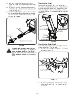
Connect the stub shaft to the backside of the ‘A’ frame
10.
bracket as shown in Figure 2. Mount the stub shaft using
the hex screws and hex lock nuts shown in Figure 2. When
mounting the stub shaft be sure that the grease fitting is
facing downward.
Re-install the front hitch with the stub shaft in place.
11.
Mount the drive shaft the stub shaft as shown in Figure 3.
12.
section 6: unpacking
Unpacking the Snow Blower
Move the tractor and snow blower to a firm flat area large enough
to accommodate both. Allow enough room to install the snow
blower on the front of the tractor.
Carefully open the shipping container. Cut any ties or bands
•
securing the snow blower, chute assembly, drive shaft, chute
crank and front hitch PTO to the shipping pallet. Remove the
snowblower, chute assembly, drive shaft, chute crank and
front hitch PTO from the shipping container.
Remove the hardware from the manual bag. Check that the
•
parts in the manual bag and the parts that came attached to
the crate are correct by referring to Figure 1 and the list on
page 3.
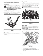
section 7: installation
Installing the Snow Blower
If your front hitch is equipped with the angle kit, the hitch angle
cylinders will need to be replaced. Follow the instructions below to
replace the cylinders.
WARNING! Do not disconnect hydraulic lines until
all system pressure is relieved. Lower the
attachment to ground, stop engine, and operate
all hydraulic control levers
Disconnect the angle kit hoses from the tractor hydraulic
1.
couplers, and slide the hoses out of the protective sleeve.
From either side of the tractor, remove the hex lock nuts, hex
2.
screws, washers, and spacers securing the cylinder to the
hitch ‘A’ frame and mounting bracket. Reassembly and Insert
the hardware in the appropriate cylinder ends and loosely
fasten with the hex lock nut to store the cylinder assembly.
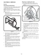
Move to the other side the tractor and repeat the above step
3.
to remove the cylinder on that side of the tractor.
Remove the cotter pins and clevis pins from the fixed length
4.
hitch arms.
From either side of the tractor, align the shorter hub of the
5.
hitch arm with mounting bracket at the bottom of the hitch
bracket, and insert the shorter clevis pin. Secure with the
cotter pin.
Raise the longer hub end of the hitch arm up between the
6.
mounting brackets on the bottom of the ‘A’ frame. Insert the
longer clevis pin and secure with the cotter pin.
Move to the other side of the tractor and repeat the previous
7.
two steps to install the fixed length hitch arm on that side of
the tractor.
Stub Shaft
Hex Screw
Hex Lock Nut
figure 2
Stub Shaft
Drive Shaft
figure 3
Summary of Contents for 59A40051727
Page 17: ...17 Notes page ...