Cub Cadet 59A40051727 Operator'S Manual Download Page 14

14

section 9: service

Service
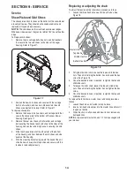
Shave Plate and Skid Shoes

The shave plate and skid shoes on the bottom of the snow blower 
are subject to wear. They should be checked periodically and 
replaced or flipped when necessary.

note: 

The skid shoes on this machine have two wear edges. 

When one side wears out, they can be rotated 180° to use the other 
edge. 
To Replace skid shoes:

Remove the six carriage bolts, hex nuts, and bell washers 

1. 

that secure the two skid shoes to the sides of the auger 
housing. Refer to Figure 17.

Position the new skid shoes and secure with the carriage 

2. 

bolts, bell washers, and hex nuts. Make certain the skid 
shoes are adjusted to be level. Refer to Figure 17.

To replace shave plate:

Remove the hex nuts, bell washers, and carriage bolts that 

1. 

secure the shave plate to the bottom of the snow blower 
housing. See Figure 17.
Remove the rear most hex nut, bell washer, and carriage 

2. 

bolt securing the back of each skid shoe to the sides of the 
housing. Loosen the remaining hex nuts securing the skid 
shoes.
Slide the shave plate out of the off-set slot at the bottom 

3. 

of the housing, and from between the skid shoes and side 
panels of the housing.
With the mounting holes facing toward the back of the unit, 

4. 

slide the new shave plate into position and secure with the 
fasteners removed previously.

figure 17

Replacing or adjusting the chain

To adjust the tension on the roller chain, proceed as follows:

Loosen the three hex bolts on each side of the box. See 

1. 

Figure 18.

To tighten the roller chain, loosen the top and middle hex 

2. 

nuts. Then while holding the bottom hex nut loosen the hex 
screw. See Figure 18.
Once the desired tension is reached, re-tighten the top and 

3. 

middle hex nuts.
To loosen the roller chain, loosen the top and middle hex 

4. 

nuts. Then while holding the bottom hex nut tighten the hex 
screw.
Once the desired tension is reached, re-tighten the top and 

5. 

middle hex nuts.

To replace the roller chain, master link or add links proceed as 
follows:

Loosen the chain as instructed in step 3 above.

1. 

Insert a flat-head screwdriver into the master link and twist it 

2. 

to open up the link.
When the chain is off you can add new links or replace any 

3. 

damaged links. 

NOTE:

 A replacement master link, and 1/2 link is packaged with 

your manual.

Middle Hex Nut

Bottom Hex Nut

Top Hex Nut

Master Link

Hex Screw

Hex Bolt

figure 18

Summary of Contents for 59A40051727

Page 1: ...Cub Cadet Yanmar LLC P o Box 368023 Cleveland Ohio 44136 0019 PRINTED IN U S A Operator s Manual 45 Snowblower Model 59A40051727 769 04374A November 13 2008 ...

Page 2: ...er housing A sample model plate is shown below For future reference please copy the model number and the serial number of the equipment in the space below Calling Customer Support If you have difficulty with this snow blower have any questions regarding the controls operation or maintenance of this equipment or desire additional information not found in this manual contact your nearest authorized ...

Page 3: ... this Operator s Manual Do not operate until control lever and equipment movements are correct Preparation Check that all hardware is tight and properly installed Always 1 tighten to torque specifications as instructed in this manual Air in hydraulic systems can cause erratic operation and allows 2 loads or equipment components to drop unexpectedly Before operating or allowing anyone to approach t...

Page 4: ... attachment adjust to outdoor temperature 18 before starting to clear snow Operational Do not allow other people in the area when operating 1 attaching removing assembling or servicing equipment particularly small children Improper use of a snow thrower can cause injury or death 2 Do not put hands or feet near or under rotating parts in the 3 auger impeller housing or discharge chute Keep clear of...

Page 5: ...rienced Cub Cadet Yanmar dealer Incorrect adjustment can result in system failures and serious personal injury Always wear relatively tight and belted clothing to avoid 3 entanglement in moving parts Wear sturdy rough soled work shoes and protective equipment for eyes hair hands hearing and head Do not allow other people in the area when operating 4 attaching removing assembling or servicing equip...

Page 6: ... AND AUGER CONTACT WITH IMPELLER OR AUGER CAN AMPUTATE HANDS AND FEET DISENGAGE PTO STOP ENGINE SET PARK BRAKE AND REMAIN ON MACHINE UNTIL ALL MOVING PARTS HAVE STOPPED BEFORE UNCLOGGING OR SERVICING TO AVOID THROWN OBJECTS INJURIES NEVER DIRECT DISCHARGE AT BYSTANDERS USE EXTRA CAUTION WHEN OPERATING ON GRAVEL SURFACES READ OPERATOR S MANUAL FOR BALLAST REQUIREMENTS REFER TO YOUR ATTACHMENT MANUA...

Page 7: ...re instructions covering in stallation safe operation and maintenance of the Model 59A40051727 snow blower assembly Please read and understand what it says The Model 59A40051727 45 Snow Blower assembly is designed for use only with certain Cub Cadet Yanmar tractor models It will NOT fit nor operate safely or properly on or with any other tractor References to LEFT and RIGHT indicate the left and r...

Page 8: ...ain 713 04069 1 pc 6 Link Connecting Chain 713 04072 1 pc 7 Cotter Pin 714 04040 2 pc 8 Shear Pin 375 x 181 738 04155 2 pc 5 8 packaged with manual 9 Chute Assembly N A 1 pc 10 Chute Clamp 703 4080 1 pc Figure 1 11 Chute Clamp Spacer 703 4079 1 pc 12 Carriage Screw 1 4 20 x 1 00 710 0932 2 pc 13 Hex Lock Nut 1 4 20 712 0324 2 pc 14 Flange Lock Nut 3 8 16 712 04065 2 pc 15 Flange lock Nut 5 16 18 7...

Page 9: ...he parts in the manual bag and the parts that came attached to the crate are correct by referring to Figure 1 and the list on page 3 SECTION 7 INSTALLATION Installing the Snow Blower If your front hitch is equipped with the angle kit the hitch angle cylinders will need to be replaced Follow the instructions below to replace the cylinders WARNING Do not disconnect hydraulic lines until all system p...

Page 10: ...w to adjust skid shoes Remove the clevis pin and click pin from the jack stand move 17 the jack into the third hole and replace the clevis pin and click pin Repeat on the other side See Figure 6 Start the tractor Using the implement control lever lower the 18 front hitch A frame Slowly driving the tractor forward align the top of the front 19 hitch A frame with the side channels of the snow blower...

Page 11: ...ower drive shaft Stub Shaft Drive Shaft A Frame not show for clarity Figure 8 Mounting the Chute NOTE Grease the chute base before attaching See Figure 9 The chute was shipped with two of the chute clamps attached To attach the chute place it onto the chute base and secure it with the one remaining chute clamp using the clamp spacer 1 4 20 x 1 00 carriage screw and 1 4 20 hex lock nut from the scr...

Page 12: ...sing is just off the ground Adjust the skid shoes to a lower position to raise the shave plate off the ground when clearing uneven areas such as a ribbon type driveway or a gravel driveway NOTE If you choose to operate the snow blower on a gravel surface keep the skid shoes in posi tion for maximum clearance between the ground and the shave plate To adjust the skid shoes Adjust skid shoes by loose...

Page 13: ... Cub Cadet Chain Lube 2 Replace the cover and secure with the previously removed 3 hex nuts SECTION 8 Maintenance Maintenance WARNING Before lubricating repairing or inspecting place tractor on a firm and level surface Place the PTO in the disen gaged OFF position set the parking brake shut engine off and remove key to prevent unintended starting Chute Directional Control The base of the discharge...

Page 14: ...bottom 3 of the housing and from between the skid shoes and side panels of the housing With the mounting holes facing toward the back of the unit 4 slide the new shave plate into position and secure with the fasteners removed previously Figure 17 Replacing or adjusting the chain To adjust the tension on the roller chain proceed as follows Loosen the three hex bolts on each side of the box See 1 Fi...

Page 15: ...o follow the contour of the ground Use the skid shoes to adjust the snow blower height in this position NOTE The blower should be operated in the float position to prevent excessive wear to the skid shoes Lower Hitch Raise Hitch Hitch Float Angle Right Angle Left Pull up Implement Control Lock Lever Snow Blower Float Right Raise Left Lower Figure 19 Engaging the Snow Blower Sit on the operator s s...

Page 16: ...Reposition the hitch pin to engage the holes in the snow 7 blower mounting frame Chute Crank To turn the chute to the right rotate the chute crank clockwise To turn the chute to the left rotate the chute crank counter clockwise Chute Clean Out Tool Warning Never use your hands to clear a clogged chute assembly Shut off engine and remain behind handles until all moving parts have stopped before unc...

Page 17: ...17 Notes page ...

Page 18: ...18 Section 12 PARTS LIST Snow Blower ...

Page 19: ...nk 2 46 713 04072 Chain Half Link 1 47 714 0126 Hi Pro Key 1 48 714 0135 Woodruff Key 1 Ref No Part Number Description Qty 49 714 0145 Click Pin 2 50 714 04040 Bow Tie Cotter Pin 8 51 714 04059 Hi Pro Key 1 52 714 0507 Cotter Pin 1 53 715 0118 Spirol Pin 5 16 1 75 2 54 715 0129 Spirol Pin 125 x 812 4 55 715 0138 Roll Pin 1 8 x 63 1 56 715 3003 Spirol Pin 1 57 716 0102 Snap Ring 2 58 717 04641 Driv...

Page 20: ...ine Shaft 1 3 712 0429 Hex Lock Nut 5 16 18 2 4 716 0102 Shaft Snap Ring 2 5 716 0188 Retainer Ring 1 6 717 04642 Drive Shaft 1 7 719 3172 Shaft 1 8 721 0462 Grease Seal 1 31 x 1 00 1 9 737 3000 Lube Fitting 1 10 741 0131 Ball Bearing 1 00 ID x 2 00 OD 1 11 741 0363 Bearing 1 000 x 1 3125 x 7500 1 PTO Drive System ...

Reviews: