10
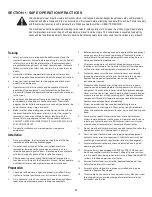
Align the locking collar of the drive shaft with the Mid - PTO
13.
shaft and slide the drive shaft fully onto the PTO shaft. If
necessary, compress the locking collar of the drive shaft to
ease connecting the shaft. See Figure 4. The intermediate
drive shaft must be securely connected to the Mid PTO shaft
at the lower/front of the tractor’s transmission housing.
WARNING! Never position any part of your body
beneath tractor implements held in the raised
position only by the tractor’s hydraulic system. A
sudden loss of pressure could cause the imple-
ment to fall and could result in severe injury.
Pull the drive shaft to make sure it is locked onto the PTO
14.
shaft. The drive shaft must not pull off of the Mid PTO shaft.
NOTE:
It may be necessary to turn the PTO slightly to align the
splines of the drive shaft with those of the PTO shaft.
Place the snow blower on a level surface.
15.
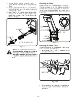
Lower the skid shoes into the lowest operating position. See
16.
Figure 5. See the Adjustments section for how to adjust skid
shoes.
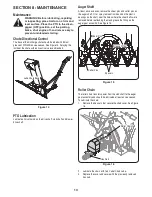
Remove the clevis pin and click pin from the jack stand, move
17.
the jack into the third hole and replace the clevis pin and click
pin. Repeat on the other side. See Figure 6.
Start the tractor. Using the implement control lever, lower the
18.
front hitch ‘A’ frame.
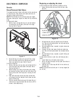
Slowly driving the tractor forward, align the top of the front
19.
hitch ‘A’ frame with the side channels of the snow blower
mounting frame. Refer to Figure 7.
Using the implement control lever, slowly raise the front hitch
20.
while making sure the hitch ‘A’ frame engages the channels
of the snow blower mounting frame. Refer to Figure 7.
As you continue to raise the front hitch, the ramp at the top of
21.
the ‘A’ frame should push the snow blower hitch pin outward,
allowing the ‘A’ frame to fully engage the snow blower mount-
ing frame and also aligning the hitch pin with the hole in the
front of the ‘A’ frame. The compression spring on the hitch pin
should push the pin through the ‘A’ frame hole to secure the
snow blower to the front hitch. See Figure 7.
Front Hitch
“A” Bracket
Snow Blower
Mounting Frame
figure 7
Jack Stand
Clevis Pin
Click Pin
figure 6
Skid Shoe
figure 5
Mid-PTO
Shaft
Locking Collar
Drive Shaft
figure 4
Summary of Contents for 59A40051727
Page 17: ...17 Notes page ...


