


19
Ref.
No.
Part
Number
Description
Qty.
1.
05244B
Bearing Housing
10
2.
603-04598
Housing Assembly
1
3.
603-04600
Chute Assembly
1
4.
603-04673
Bracket Assembly
1
5.
603-04689
Chain Cover
1
6.
618-04800
Auger Gear Assembly
1
7.
684-0090B
Impeler Assembly
1
8.
684-04056
Chute Cleanout tool
1
9.
684-04329
Spiral Assembly, RH
3
10.
684-04330
Spiral Assembly, LH
3
11.
703-05048
Rubber Chute Bracket
1
12.
703-06972
Chute Deflector
1
13.
703-07066
Stand Bracket
2
14.
703-07168
Spacer Plate
2
15.
703-4079
Chute Clamp Spacer
3
16.
703-4080
Chute Clamp
3
17.
710-0376
Hex Screw, 5/16-18 x 1.00
2
18.
710-0451
Carriage Bolt, 5/16-18 x .750
13
19.
710-0514
Hex Screw, 3/8-16 x 1.00
6
20.
710-0726
Hx. Wshr. Screw, 5/16-20 x .750
1
21.
710-0932
Carriage Screw, 1/4-20 x 1.00
6
22.
710-0946
Machine Screw, 1/4-20 x .625
3
23.
710-1207
Hex Screw, 5/16-18 x 3.50
2
24.
710-3008
Hex Screw, 5/16-18 x .75
1
25.
710-3015
Hex Screw, 1/4-20 x .75
2
26.
710-3038
Hex Screw, 5/16-18 x .875
7
27.
710-3085
Hex Screw, 3/8-16 x 3.50
2
28.
710-3105
Carriage Bolt, 5/16-18 x .875
2
29.
710-3168
Carriage Bolt, 3/8-16 x 1.00
2
30.
710-3178
Carriage Bolt, 3/8-16 x .75
4
31.
710-3180
Hex Screw, 5/16-18 x 1.75
1
32.
710-3251
Hex Screw, 5/16-18 x 1.75
1
33.
711-0173
Clevis Pin
2
34.
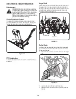
711-05107
Input Shaft
1
35.
712-0130
Hex Lock Nut, 3/8-16
6
36.
712-0298
Jam Nut, 1/4-20
2
37.
712-0324
Hex Lock Nut, 1/4-20
6
38.
712-04063
Flange Lock Nut, 5/16-18
31
39.
712-04064
Flange Lock Nut, 1/4-20
7
40.
712-04065
Flange Lock Nut, 3/8-16
2
41.
712-3010
Hex Nut, 5/16-18
8
42.
713-04066
Sprocket
1
43.
713-04067
Sprocket
1
44.
713-04068
Roller Chain
1
45.
713-04069
Chain Connecting Link
2
46.
713-04072
Chain Half Link
1
47.
714-0126
Hi-Pro Key
1
48.
714-0135
Woodruff Key
1
Ref.
No.
Part
Number
Description
Qty.
49.
714-0145
Click Pin
2
50.
714-04040
Bow-Tie Cotter Pin
8
51.
714-04059
Hi-Pro Key
1
52.
714-0507
Cotter Pin
1
53.
715-0118
Spirol Pin, 5/16-1.75
2
54.
715-0129
Spirol Pin, .125 x .812
4
55.
715-0138
Roll Pin, 1/8 x .63
1
56.
715-3003
Spirol Pin
1
57.
716-0102
Snap Ring
2
58.
717-04641
Drive Shaft
1
59.
720-0201A
Chute Crank Knob
1
60.
720-0241
Wing Nut
2
61.
726-0100
Push Cap
1
63.
731-05163
Spcer., 1.50 OD x 1.00 ID x 1.00
12
64.
732-3091
Compression Spring, .57 x 2.09
1
65.
735-04154
Rubber Deflector
1
66.
736-0105
Washer, .401 x .870 x .063
6
67.
736-0123
Flat Washer, .349 x 1.16 x .064
2
68.
736-0140
Flat Washer, .385 x .62 x .063
1
69.
736-0242
Bell Washer, .340 x .872 x .060
8
70.
736-0250
Flat Washer, 1.00 x 1.75 x .107
4
71.
736-0270
Bell Washer, .265 x .75 x .062
2
72.
736-0343
Flat Washer, .330 x 1.25 x .120
1
73.
736-0451
Saddle Wshr., .320 x.93 x .060
3
74.
736-3072
Flat Washer, .36 x .93 x .110
6
75.
738-0255
Shoulder Screw, .375 x .181
4
76.
738-04155
Shear Pin, .25 x 1.75
8
77.
738-04159
Spiral Axle
1
78.
741-04024
Self-Aligning Bearing
1
79.
741-04132A
Self-Aligning Bearing
2
80.
741-0475
Plastic Bushing
3
81.
741-0494
Flnge. Bshg., 1.05 ID x 1.16 OD
12
82.
747-04188
Chute Crank Rod
1
83.
747-0481A
Eye Bolt, 5/16-18 x 3.0
2
84.
747-0903
Chute Crank Rod, .375 x 36.75
1
85.
747-3427
Front Hitch Pin
1
86.
749-04549
Crank Support Tube
1
87.
749-04552
Support Tube
1
88.
750-04020
Spacer, 1.004 x 1.375 x .25
2
89.
750-05176
Spacer, 3/8 ID x 1.0 x 2.25
2
90.
784-5076
Gear Housing Support Bracket
1
91.
784-5123
Chute Crank Bracket
1
92.
784-5149
Bracket Assembly Joint
2
93.
784-5401
Chute Crank Assembly
1
94.
784-5696B
Shave Plate
1
95.
784-5697
Skid Shoe
2
96.
784-5710
Support Plate
1
97.
790-00181
Blade Guide
2
Summary of Contents for 59A40051727
Page 17: ...17 Notes page ...