background image

MACHINE TERMS 

Label Placement

: The time from when the product sensor is made to when the labeling sequence 

starts. 

 
Label Sensor

: The sensor that detects the leading or trailing edge of the label. 


Label Size

: The width and length (or feed) of a label. Length equals the distance from the leading 

edge of the label to its trailing edge. Width is the distance across the label. 
 

Leading Edge: 

Refers to the signal sent from a sensor when the first edge of a product or label is 

detected. 

 
LED

: Light Emitting Diode 


Normal Tamp Blow

: A mode of operation where a label is dispensed onto the label pad and the 

applicator waits for the product detect sensor to turn on before starting the labeling sequence. 

 
Parity

: A data bit that provides a means of checking for errors in the data stream. 


Peel Edge

: A machined part just before the label pad used to transfer the label onto the pad as the 

liner is pulled around the part. 
 

Rewind

: This is the rotating mandrel that takes up the liner after the labels have been removed. 


Static Stack

: When labels are applied to a stationary target on top of each other to check 

repeatability of the applicator. 
 

Tamp/Swing Extend Time

: The time allowed for the tamp slide to fully extend. 


Tamp/Swing Retract Time

: The time allowed for the tamp slide to return from it’s extended 

position to it’s retracted position. 
 

Trailing Edge

: Refers to the signal sent from a sensor when the last edge of a product or a label 

is detected. 
 

Unwind

: The rotating mandrel where the roll of labels is placed to be printed and applied. 


Valve Bank

: The typical valve bank for a tamp has three valves in it. Each valve has a built in 

regulator and gauge. The assembly is made to be bolted on either side of the applicator. 
 

Warning Alarm: 

This alarm serves as a warning that the applicator is low on labels or ribbon. 

 
Web Path

: The path the label liner follows leading from the unwind, through the printer and ends 

at the rewind. 


                                                                                                                                               4-2 

Summary of Contents for 3600-PA

Page 1: ...HIO 44460 PHONE 330 332 1800 FAX 330 332 2144 www ctmlabelingsystems com Designers and Manufacturers of Pressure Sensitive Labeling Equipment and Custom Product Handling 3600 PRINTER APPLICATOR MAINTENANCE SERVICE MANUAL REVISION 3600 2b5 x ...

Page 2: ...ard Tamp Installation 7 3 Extended Peel Edge Installation 7 4 Swing Tamp Installation 7 5 Ribbon and Label Loading 7 6 Applicator Nose Setup 7 7 Tamp Setup 7 8 Static Stack Test 7 9 Configuration Menus 7 10 PRODUCT SETUP 8 Applicator Attitudes 8 1 Applicator Position 8 2 Product Detect Sensor SM312LV 8 3 Product Detect Sensor S18SN6FF50 8 4 APPLICATOR ALARMS 9 Alarm Light 9 1 Systems Ready Output ...

Page 3: ... 11 PRINTER SETTINGS 12 Sato Printers 12 1 Zebra Printers 12 7 Datamax Printers 12 7 RECOMMENDED SPARE PARTS 13 AND DRAWINGS SUPPLIMENTS TO STANDARD 3600 MANUAL Dual Action Tamp Section B Corner Wrap Section C Powered Unwind Section D ...

Page 4: ...e 8 1 FIGURE 10 Applicator in Bottom Up Attitude 8 1 FIGURE 11 Applicator in Reels Up Attitude 8 1 FIGURE 12 SM312LV Product Detect Sensor 8 2 FIGURE 13 S18SN6FF50 Product Detect Sensor 8 3 FIGURE 14 Alarm Light 9 1 FIGURE 15 Low Label Sensor on Unwind Block 9 2 FIGURE 16 Low Label Sensor 9 2 FIGURE 17 Unwind Brake Band 10 2 FIGURE 18 Rewind Clutch Assembly 10 3 FIGURE 19 DAT Valve Bank b5 1 FIGUR...

Page 5: ... FIGURE 24 S18SN6FF50 Product Detect Sensor b6 3 FIGURE 25 Apply Sequence c3 1 FIGURE 26 Apply Sequence c3 2 FIGURE 27 Apply Sequence c3 3 FIGURE 28 Corner Wrap Valve Banks c3 4 FIGURE 28 Web Path Powered Unwind d2 1 2 ...

Page 6: ...off the pad and onto the product In the Inverted Tamp Blow mode the label is printed dispensed onto the label pad and the slide extends The applicator will wait in this position until the product sensor is made The label is then blown off the pad onto the product For safe and trouble free operation the instructions in this manual must be followed carefully during the set up operation media changes...

Page 7: ...icator may not operate properly WORK CAREFULLY Although setting up the applicator is not difficult it does take time Do not rush through the process Careful work will produce good results IF SOMETHING DOES NOT WORK PROPERLY TRY SETTING UP AGAIN Although applicator malfunction is possible most problems happen because the applicator was not setup correctly If the applicator doesn t operate correctly...

Page 8: ......

Page 9: ......

Page 10: ......

Page 11: ......

Page 12: ......

Page 13: ......

Page 14: ......

Page 15: ......

Page 16: ......

Page 17: ......

Page 18: ... the unwind when labels are being printed and to stop the unwind mandrel when printing stops Detector Lockout Time span after the applicator starts the labeling sequence that will cause the applicator to ignore any additional product signals This is useful if a product triggers the product detect sensor more than once Extended Air Assist The air assist is always on while the label is being printed...

Page 19: ...o the pad as the liner is pulled around the part Rewind This is the rotating mandrel that takes up the liner after the labels have been removed Static Stack When labels are applied to a stationary target on top of each other to check repeatability of the applicator Tamp Swing Extend Time The time allowed for the tamp slide to fully extend Tamp Swing Retract Time The time allowed for the tamp slide...

Page 20: ...tting the label in the right position on the product Tamp Extend Time Time allowed for the tamp slide to extend before continuing with the labeling sequence Tamp Retract Time Time allowed for the tamp slide to return to receive a label from the extended position Air Blast Time Time the air blast valve will stay on Extended Air Assist The air assist is on as long as the applicator is printing a lab...

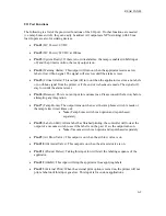
Page 21: ...led line should start to flash Use the arrow keys to toggle the line so it says Tamp Is Disabled Press Ent when the line matches what the applicator is to do Note Short cuts to enable and disable the tamp are as follows Pressing will disable tamp Pressing will enable tamp To change numeric data go to the menu to be changed i e Label Placement using the menu key Press Ent and the timer data will se...

Page 22: ... sensor mounted on the unwind of the applicator Low Ribbon signal from the printer No Label Ribbon signal from the printer End of Web signal from sensor looking for the end of the label stock Too Many Reprints signal from the Label Reprint counter triggered when more labels have been pulled off the pad than the preset amount 5 3 ...

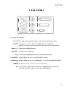
Page 23: ...t sensor connection LOW LBL Low label sensor connection AUX Used for End of Web sensor connection or custom applications PARALLEL Wired to the parallel port of the printer for data transfer ETHERNET In place of parallel port Used to transfer data to ethernet equipped print engines SERIAL Wired to the serial port of the printer for data transfer I O This connector can be used for integrators to mon...

Page 24: ...reset Pin 6 Reissue This is not an input for customer use Please consult the factory before attempting any integration Pin 7 Tamp Home The output turns on when ever the tamp home switch is made or the tamp retract timer times out Note Tamp home switch is an option and is purchased separately Pin 8 Label on Pad After a label has finished printing the controller will look at the output of a vacuum s...

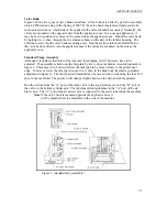
Page 25: ...figured so the unwind can be positioned in different locations to aid in certain applications Figure 1 unwind assembly Unwind disks The unwind disks include a Lexan disk and hub screwed together The inboard assembly will have two holes in the disk for the low label sensor The outboard assembly will have a solid disk and hub assembly that includes a ratchet handle for locking it in place Place the ...

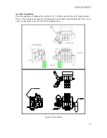
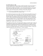
Page 26: ...or is shipped the air filter is off The filter is sent with two 2 nipples and an elbow The attitude of the machine will determine how the filter should be plumbed Note In all cases it is important to have the filter bowl pointing down Figure 2 Valve Banks 7 2 ...

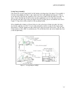
Page 27: ... Assembly Although it is unlikely that this will be removed for shipping it will however have to be adjusted The assembly is held onto the faceplate by two shcs marked as in out adjustment in figure 3 These same two bolts will allow the label pad to be moved closer to the printer peel edge To raise or lower the label pad loosen two shcs in the slide body marked as up down adjustment in figure 3 Th...

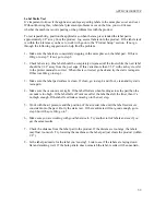
Page 28: ...cs marked as tamp in out adjustment in Figure 4 When the label pad is in position re tighten the screws To raise or lower the label pad to the peel edge loosen the two shcs in the slide body marked as up down in Figure 4 The label pad can be moved side to side using the four 10 shcs in the manifold To move the whole assembly in or out so the peel edge lines up with the leading edge of the label lo...

Page 29: ...ry actuator Moving the label pad closer to the peel edge is done by loosening the in out adjustment screws in Figure 5 These also hold the actuator to the mounting bracket When plumbing the actuator air that enters on a side on the top rack must also enter the lower rack on the opposite end The A port on the tamp valve needs to connect to the top rack port farthest away from the applicator body an...

Page 30: ...2 Load a roll of labels onto the hubs on the unwind shaft Make sure the labels are against the inner disk and are right side up 3 Remove the first three feet of labels from the liner 4 Thread the label stock around the dancer and guide rollers into the printer Refer to Figure 6 for the web path from the unwind to the printer Refer to the printer manual as to how to thread the printer Make sure the...

Page 31: ...e label could come into contact with the peel bar of the printer when the tamp slide extends If the label pad is too low the label will dispense into the back of the pad and jam 4 The inboard edge of the label pad must match the inboard side of the label Refer to the side to side adjustments to move the pad 5 Position the air assist tube so the hole or holes are centered on the label and pointing ...

Page 32: ...l section as to where these menus are Tamp extend time needs to be set so the slide fully extends before the air blast turns on If the blow off occurs too soon the label application will not be accurate If the time is too long it adds to cycle time and will slow label rate Tamp return time is the time allowed for the slide to return home before printing another label If this time is too short the ...

Page 33: ...rect When this is corrected go back and try the static test again If this was OK go to step 3 3 Make sure the label pad surface is clean If clean go to step 4 and if not clean and try static test again 4 Make sure the vacuum is set right If the label flutters when feeding across the pad then the vacuum is too high If the label falls off or moves after the label has left the liner then it s not hig...

Page 34: ...etween Normal and ITB When you get what you want press ENT Press MENU to go to the Printer Type screen Printer Type The 3600 PA will support both Sato and Zebra printers There are some slight differences between the printers on how they handle the recovery from a fault condition The Zebra printer will dispense a group labels after a critical fault whether it gets a print start signal or not This m...

Page 35: ... 2 5 then divide by 2 1 2 This value 1 2 is your threshold value Enter this value in the sub display by the up and down arrow keys Note If the vacuum pressure is increased or decreased you may have to adjust the threshold value per above example Vacuum Off Option This option is used to turn the vacuum to the label pad on and off to save air and to keep particles from entering the pad when there is...

Page 36: ...Note Factory default values are Delay On 0 seconds Delay Off 1 second To change timer variables see the Changing Variable Fields of the Applicator Display section Tamp Home Option With software version 2b5 4 a Tamp Home Option was added in the configuration menu to determine the Tamp Home output by the Tamp Retract Time or Tamp Home switch When the Tamp Home Option is selected as Tamp Retract Time...

Page 37: ...able External Reprint in the Advanced Mode settings of the print engine When using the Sato printer the Label Reissue option will print the last format sent until a new format is received Label Reprint Option With this option is turned on and a vacuum switch installed the applicator will dispense another label when the label is removed from the label pad This option is useful when an extra label i...

Page 38: ...tion and have trouble with the application here it will leave you with more areas to troubleshoot to fix the problem Applicator Attitudes The applicator can be positioned in a number of positions Below applicators are shown in different attitudes with the proper name under it Figure 7 nose down Figure 8 upright and above Figure 9 nose up Figure 10 bottom up Figure 11 reels up 8 1 ...

Page 39: ...r the application point Now position the product detect sensor slightly upstream of the leading edge of the product Now go to the product sensor setup that matches your sensor and follow directions Standard Product Sensor Setup Banner SM312LV 4 15 range 1 Plug the sensor into the back of the machine 2 Turn the power on and disable the tamp 3 Remove the back cover of the sensor and set the light da...

Page 40: ...f the sensor cable is for the output of the sensor The black wire is for leading edge and the white wire for trailing edge Figure 13 optional product detect Label Placement Moving the label to the correct position to flow is best accomplished by moving the product detect For fine adjustments or to adjust while the line is running the operator can change the label placement value in the display The...

Page 41: ...bel and ribbon alarms come from the printer and you should consult the printer manual as to how the signals are set The end of web signal comes from a sensor mounted to look for the label supply to end before entering the printer On a critical alarm the applicator will stop applying labels To reset the alarms the display will instruct the operator to press the ENT key Before clearing the alarm mak...

Page 42: ...e the back cover of the sensor and set the light dark switch to DO by turning the switch counter clockwise 4 Look at the red dot shining from the sensor to the unwind disk The red dot shows what the diameter of the roll will be when the alarm turns on To turn the alarm on sooner move the sensor up so that it is farther away from the core To turn the alarm on later move the sensor down closer to th...

Page 43: ...llection Drain if necessary 3 Examine the tamp pad and the rollers used to guide the web for adhesive build up Clean if needed with alcohol or similar solvent 4 Look for loose screws rollers etc Weekly Maintenance 1 Clean peeler bar rollers and tamp pad 2 Examine machine for air leaks 3 Wipe down the outside of the applicator and product detect lens 4 On extended peel edge noses check the uhmw tap...

Page 44: ... the unwind disks are tight against the roll of labels will help 1 Hold the dancer arm in the position it should be when the brake is on Loosen the collar that the brake band is anchored to rotate it so the band is tight and tighten back down Make sure the brake band is wound in the right direction 2 Loosen the collar with the spring anchor and tighten so the dancer arm is held up with enough tens...

Page 45: ...o the machine 2 Remove the lower stainless cover 3 CAREFULLY remove the tension adjustment screw and all washers NOTE the spring is under compression load Keep track of how many flat washers are on the outboard and inboard sides of the spring washer 4 If the rewind tension was too tight move one or two of the flat washers from the outboard side of the spring washer to the inboard side nested insid...

Page 46: ...en re assembled 4 Work the belt off the pulley pressure plate and slip off the pressure plate 5 Replace the clutch pad 6 Re assemble and adjust the tension for the new clutch pad Belt Tension 1 Remove power and air to the machine 2 Remove the stainless cover on the back of the applicator 3 Proper Tension 1 4 3 8 Belt Deflection 4 Loosen the two socket head cap screws that bolt through the side of ...

Page 47: ... cord in Label liner breaking Labels are not threaded correctly Unwind rewind disks or guide collar not aligned with printer Adhesive build up Label jammed in printer Bad roll of labels Re thread labels Adjust disks and collars so the labels flow through the printer Clean as necessary Clear jam Replace label roll Labels are not consistently stopping on label pad Vacuum pump not working Too little ...

Page 48: ...o it is repeatable Enter a higher value for the tamp extend time Install the right label pad Valves do not turn on Air pressure is too low Valve bank plug is not connected to the applicator Valve spool is stuck Bad solenoid Dwell times to short Turn air pressure above 20 psi and try again The air assist valve is different and can operate at a lower pressure Connect the valve bank plug Consult fact...

Page 49: ...e dwell times for air blast tamp extend retract or air assist The label print and apply cycle may be too long for the product rate Check software and compiling time increase print speed Go through the setup procedure for proper setting Slow product rate Applicator cycles at random Loose or vibrating product detect sensor Product detector alignment is marginal Loose wiring connections R F interfere...

Page 50: ...uch tension on it Re adjust slip clutch Printing registration is late Rewind tension is too tight not allowing a complete back feed Re adjust slip clutch Poor print quality Refer to printer manual Labels print continuously without being applied Printer configuration is wrong Print end signal was not received from printer Lost 24 vdc power supply Check printer settings Call factory for help Alarm m...

Page 51: ...W2 and DSW3 located inside the cover These switches are used to set Thermal transfer or direct thermal Label sensor enable disable Head check mode Hex dump mode Single job or multi job receive buffer Operation mode A third dipswitch is located on the RS232 serial adapter card back of the printer This is used to setup the serial communications If the switches are down they are off Factory settings ...

Page 52: ...lection These switches select the type of parity used for error detection DSW1 2 DSW1 3 SETTING Off Off Disabled Off On Even On Off Odd On On None Stop Bit Selection Selects the number of stop bits to end each byte transmission DSW1 4 SETTING Off 1 Stop Bit On 2 Stop Bit Baud Rate Selection Selects the data rate bps for the RS232 port DSW1 5 DSW1 6 SETTING Off Off 9600 Off On 19200 On Off 38400 On...

Page 53: ...on thermally sensitive paper and thermal transfer printing using a ribbon This switch is not used on the M 8459 DSW2 1 SETTING Off Therm Xfr On Direct Thrm Note It is recommended that this be set to Off Sensor Type Selection Selects between the use of a label gap or a reflective Eye Mark detector DSW2 2 SETTING Off Gap On Eye Mark Note It is recommended that this be set to Off Head Check Selection...

Page 54: ...the receive buffer DSW2 5 SETTING Off Single Job On Multi Job Protocol Code Selection Selects the command codes used for protocol control DSW2 7 SETTING Off Standard On Non Std M8400 Emulation Mode For emulating special M8400S series software commands Should be used only if problems are encountered when using existing M8400S software DSW2 8 SETTING Off Disable On Enable 12 4 ...

Page 55: ...t the edge of the label and position it automatically If it is disabled the positioning must be under software control using line feed commands DSW3 3 SETTING Off Sensor Used On Not Used Note It is necessary to leave this switch off for the applicator to work Backfeed Selection When backfeed is enabled the printer will position the last printed label for dispensing and retract it before printing t...

Page 56: ...l synchronizing signal can be selected DSW3 6 DSW3 7 SETTING Off Off Type 4 Off On Type 3 On Off Type 2 On On Type1 Note Use Type 4 for use with the applicator Repeat via External Signal Allows the applicator to reprint the current label in the print buffer DSW3 8 SETTING Off Enable On Disable Note This has become a standard option called Reissue with Software Revision 2b5 0 Sato Printers S 8400 S...

Page 57: ...ay need to be set that are not discussed in the chart below Refer to the printer manual for the total list PARAMETER SETTING Print Mode Applicator required Media Type Non continuous required Sensor Type Web required Applicator Port Mode 2 required Start Print Signal Pulse Mode required Ribbon Low Output Active High DATAMAX A CLASS MARK II PRINTER SETTINGS PARAMETER SETTING GPIO Device Applicator 2...

Page 58: ...tion ASS 238 0124L or 1 LH 24VDC POWER SUPPLY ASSEMBLY ASS 238 0124R 1 RH 24VDC POWER SUPPLY ASSEMBLY PE FU2090 1 6 3 AMP FUSE EXTENDED SPARE PARTS LIST Part Number Recommended Qty Description ASS 200 0427 1 SM312LV PRODUCT DETECT W CONNECTOR PE RT1000 1 1 W X 6 L REFLECTIVE TAPE ASS IN1055 1 3600 OPER INTERFACE DISPLAY Program specific MP PLC1046 1 PLC Program specific PE RE1015 1 MOTOR RELAY 360...

Page 59: ... 16 POWERED UNWIND Part Number Recommended Qty Description PM FASP30434 1 DANCER ARM SPRING REWIND PE SE10108 2 PROXIMITY SWITCH W QUICK DISCONNECT PM AC1428 1 DANCER SPRING LOADED CYLINDER PM BE1305 4 LINEAR BEARING PE MC1109 1 MOTOR DRIVE CONTROLLER PE PO1030 1 5K SPEED POTENTIONMETER PE SI1050 1 ISOLATOR BOARD WEAR ITEMS Part Number Recommended Qty Description PM BELT1015 1 REWIND BELT MP 238 0...

Page 60: ...ADJUSTMENT KNOB ASSEMBLY EXTENDED SPARE PARTS STANDARD EXTENDED PEEL BAR Part Number Recommended Qty Description ASS 238 0129M 1 TAMP 3 STATION VALVE BANK ASSEMBLY PM VA2395M 1 5 4 WATT DC SOLENOID PM VA2396M 1 60 PSI AIR ASSIST REGULATOR PM VA2397M 1 120 PSI TAMP BLOW REGULATOR SLIDE ASSEMBLIES STANDARD EXTENDED PEEL BAR Part Number Recommended Qty Description ASS 214 0108 1 1 1 SLIDE ASSEMBLY AS...

Page 61: ...ed Qty Description PM INS1010 1 THREADED INSERT PM FANU30375 1 CAPTURE WASHER PM LL1002 1 LOCK LEVER EXTENDED SPARE PARTS Part Number Recommended Qty Description MP 238 0338 1 SS HEAVY WASHER PM BEBT1008 2 THRUST WASHER PM BEBF1070 2 FLANGE BUSHING PM FASB10045 2 SHOULDER BOLT MP 238 0335 1 LOCATOR BLOCK SWING AWAY TAMP SPARE PARTS LIST ...

Page 62: ...BSORBER HOME PM SA1000 1 SHOCK ABSORBER EXTEND RECOMMENDED SPARE PARTS ROTARY SWING TAMP CORNER WRAP Part Number Recommended Qty Description PM SA0990 1 SHOCK ABSORBER HOME PM SA1000 1 SHOCK ABSORBER EXTEND ROTARY ACTUATOR Part Number Recommended Qty Description PM AC1250 1 STANDARD DUTY ROTARY ACTUATOR NOTE CONTACT SALES DEPARTMENT FOR HEAVY DUTY ROTARY ACTUATOR SWING TAMP SPARE PARTS LIST ...

Page 63: ...ORBER PM SA0990 1 SHOCK ABSORBER HOME PM SA1000 1 SHOCK ABSORBER EXTEND PM BELT1039 1 TIMING BELT NOT REQ D FOR INLINE DAT SLIDE ASSEMBLIES Part Number Recommended Qty Description PM AC1237 or 1 3 SLIDE ASSEMBLY PM AC1239 or 1 6 SLIDE ASSEMBLY PM AC1241 1 8 SLIDE ASSEMBLY ROTARY ACTUATOR Part Number Recommended Qty Description PM AC1248 1 ROTARY ACTUATOR DUAL ACTION TAMP DAT SPARE PARTS LIST ...

Page 64: ...OMMENDED SPARE PARTS TOUCH AND GO TAG PHOTOEYE Part Number Recommended Qty Description PE SE0985 1 SM312W QD SENSOR JOB SPECIFIC OPTIONS RECOMMENDED SPARE PARTS TOUCH AND GO TAG MECHANICAL Part Number Recommended Qty Description PE SW1110 or 1 OMRON LIMIT SWITCH ARM STYLE PE SW1105 or 1 OMRON LIMIT SWITCH BUTTON ROLLER STYLE PE SW1100 1 OMRON LIMIT SWITCH BUTTON STYLE OPTIONS RECOMMENDED SPARE PAR...

Page 65: ...ing parts present Serial Number of 3600 OPTIONS RECOMMENDED SPARE PARTS AC INCANDESCENT ALARM LIGHT ALLEN BRADLEY Part Number Recommended Qty Description PE LI2070 1 LAMP ALARM LIGHT PE RE1001 1 RELAY ALARM LIGHT SPARE PARTS LIST FOR RETIRED ASSEMBLIES ...

Page 66: ......

Page 67: ......

Page 68: ......

Page 69: ......

Page 70: ......

Page 71: ......

Page 72: ......

Page 73: ......

Page 74: ......

Page 75: ......

Page 76: ......

Page 77: ......

Page 78: ......

Page 79: ......

Page 80: ......

Page 81: ......

Page 82: ......

Page 83: ......

Page 84: ......

Page 85: ......

Page 86: ......

Page 87: ......

Page 88: ......

Page 89: ......

Page 90: ......

Page 91: ......

Page 92: ......

Page 93: ......

Page 94: ......

Page 95: ......

Page 96: ......

Page 97: ......

Page 98: ......

Page 99: ......

Page 100: ......

Page 101: ......

Page 102: ......

Page 103: ......

Page 104: ......

Page 105: ......

Page 106: ......

Page 107: ......

Page 108: ......

Page 109: ......

Page 110: ......

Page 111: ......

Page 112: ......

Page 113: ......

Page 114: ......

Page 115: ......

Page 116: ...HONE 330 332 1800 FAX 330 332 2144 www ctmlabelingsystems com Designers and Manufacturers of Pressure Sensitive Labeling Equipment and Custom Product Handling 3600 DUAL ACTION TAMP PRINTER APPLICATOR MAINTENANCE SERVICE MANUAL REVISION 3600 dat 2b5 x ...

Page 117: ...ons b3 1 Changing Variable Fields b3 2 REAR PANEL b4 Connector Descriptions b4 1 I O Port Functions b4 2 DUAL ACTION SETUP b5 Air Filter Installation b5 1 Applicator Nose Installation b5 2 General Applicator Setup b5 3 Dual Action Tamp Setup b5 4 Static Stack Test b5 6 Configuration Menus b5 7 PRODUCT SETUP b6 Applicator Attitudes b6 1 Applicator Position b6 2 Standard Product Detect Sensor SM312L...

Page 118: ...lly extended and then returns home to repeat the cycle for the next product Exceptions to this sequence can be addressed through a custom applicator The applicator can work in two different modes Normal Tamp Blow Inverted Tamp Blow In the Normal Tamp Blow mode the label is printed dispensed out onto the label pad and held there by vacuum When the product detect sensor is made the label and label p...

Page 119: ...nge is 20 to 85 RH non condensing Note The model 3600 PA is not intended to be operated in an environment where flammable or explosive gases are present The model 3600 PA MUST not be used in direct contact with food products The following section for dual action tamp applicators will discuss items that pertain only to this applicator type Items not covered here will be covered in the standard 3600...

Page 120: ......

Page 121: ......

Page 122: ......

Page 123: ......

Page 124: ...nu This key will allow the operator to scroll through the following sub menus Label Rate This will display the rate in which labels are being applied on a per minute basis When the DAT applicator is in Dual Tamp Mode the label rate will update every apply cycle even though two labels are being applied Swing Label Placement This is the time or distance from when the product detect sensor turns on u...

Page 125: ...s screen When cycling power to the applicator the count will be reset to zero Home Tamp When scrolling through sub menus pressing Home will take you back to the main menu If you re at the main menu and tamp is enabled press the Home Tamp key to extend the tamp slide This will be helpful setup of the clearing with label jams Arrow Keys Menus that have a numeric input i e Label Placement menu use th...

Page 126: ...er will default to the previous setting after 10 seconds Note If you only need to change the numeric data by a few milliseconds or thousandths of an inch use only the arrow keys Every time an arrow key is pressed the value will be increased or decreased by one unit Example Set Label Placement to 0 115 115 ms Press Menu until the Label Placement menu is displayed Press Ent to clear timer data flash...

Page 127: ...ensor connection AUX Used for custom applications PARALLEL Wired to the parallel port of the printer for data transfer ETHERNET In place of parallel port Used to transfer data to ethernet equipped print engines SERIAL Wired to the serial port of the printer for data transfer I O This connector can be used for integrators to monitor applicator alarms and functions See the next page for a list of pr...

Page 128: ... an input for customer use Please consult the factory before attempting any integration Pin 7 Tamp Home The output turns on after the applicator has finished it s labeling cycle This means if the applicator is set to dual action tamp the output will not turn on until the end of the second label application Pin 8 Reserved For future use Pin 9 Air Blow Valve This output is on when the air blow valve...

Page 129: ...embly and ribbon label loading are covered in the standard 3600 section Air Filter Installation When the applicator is shipped the air filter is off The filter is sent with two 2 nipples and an elbow The attitude of the valve bank will determine how the filter should be plumbed Note In all cases it is important to have the filter bowl pointing down The filter should enter the valve bank on the opp...

Page 130: ...now the bottom of the applicator and extends out in front of where the label comes out of the printer There is a recess in the plate with four slots This is where the slide of the dual action tamp is mounted Take the tamp assembly and set it slide body in the recess and used the four shcs and the stainless nut plate to secure it in position These same screws will be later be used for the up and do...

Page 131: ...e extends If the label pad is too low the label will dispense into the back of the pad and jam 4 The inboard edge of the label pad must match the inboard side of the label Refer to the side to side adjustments in the next section to move the pad 5 Position the air assist tube so the hole or holes are centered on the label and pointing approximately in from the label pad The air pressure should be ...

Page 132: ...h the swing arm fully retracted Move the rotary actuator to tighten the belt and secure the screws at the A adjustment With the swing arm in the home position make sure the pad is parallel with the peel edge To rotate the label pad parallel loosen the lock nut on the D adjustment the one closest to the label pad and turn the set screw in or out When there is air to the actuator you should see the ...

Page 133: ... the shock in or out When in position re tighten the clamp so the shock will stay in position The flow controls for the slide are mounted on the valve bank Screwing the knobs in will slow the speed of the slide and turning the knobs out will speed it up Note The slide extend stop will have to be adjusted but this adjustment is discussed in the Product Setup section under Positioning the Applicator...

Page 134: ...to the printer manual to correct When this is corrected go back and try the static test again If this was OK go to step 3 3 Make sure the label pad surface is clean If clean go to step 4 and if not clean and try static test again 4 Make sure the vacuum is set right If the label flutters when feeding across the pad then the vacuum is too high If the label falls off or moves after the label has left...

Page 135: ... and the last word on the second line should start to flash Use the arrow keys to toggle between Sato and Zebra When you get what you want press ENT Press MENU to go to the next screen Tamp Action Setup This menu will let you chose from setting the applicator tamp type up from the display or from digital inputs from an external controller When it is set to remote the applicator will look at inputs...

Page 136: ...To change from one mode to the other press ENT and the second line should start to flash Use the arrow keys to toggle between Swing Tamp and Side Tamp When you get what you want press ENT Press MENU to go to the next screen Lead or Trail Apply This menu appears if the applicator is configured for dual action tamp or remote tamp This setting determines which actuator will fire first If set to lead ...

Page 137: ...der is turning the encoder may be turning the wrong direction You can physically turn the encoder around or you can reverse the white and black wires on TB1 17 and TB1 18 Input 6 Configuration This allows the operator to configure input 6 as an inhibit or as an external print input When the input is configured as an inhibit the applicator apply cycle will not actuate when the input is on When the ...

Page 138: ...ff Double Product Detect Signal This option was added so the customer could use the falling edge signal of the product detect sensor to trigger the first label of a dual action tamp sequence and the rising edge signal to trigger the second label The sequence is as follows leading dual tamp is used for the example With the product detect sensor set so when a product is in front of it the output is ...

Page 139: ...ion is useful when an extra label is needed on line but you do not want to actuate the applicator to replace the label you took from the label pad You simply pull the label off the pad and another label is printed and dispensed The Number of Reprints screen will appear after the Label Reprint screen only if Label Reprint was turned on Here the number of reprints can be preset up to 99 labels Note ...

Page 140: ...licator setup section and have trouble with the application here it will leave you with more areas to troubleshoot to fix the problem Applicator Attitudes The applicator can be positioned in other positions but the standard configuration from the factory is nose down Any other attitudes should be discussed with the factory before ordering Figure 22 nose down b6 1 ...

Page 141: ...slide forward making sure the swing arm is retracted and stop when there is about 1 8 between the product and the label pad Here you may need to move the slide extend stop see figure 5 Loosen the clamping screw and slide the stop against the slide body Some minor changes may have to be done when you start applying labels but this will get you close Standard Product Sensor Setup Banner SM312LV 4 15...

Page 142: ...mats to the printer Position the product detect sensor about 6 inches upstream of the extended swing arm Set the 1 label placement to 0 000 and turn the conveyor on Put a product on and watch when the label is blown off the label pad If the product hit the label pad before it retracted move the product detect up stream more If it retracted too soon move the sensor downstream Ideally the label will...

Page 143: ......

Page 144: ......

Page 145: ......

Page 146: ......

Page 147: ......

Page 148: ......

Page 149: ......

Page 150: ......

Page 151: ......

Page 152: ......

Page 153: ......

Page 154: ......

Page 155: ......

Page 156: ...0 PHONE 330 332 1800 FAX 330 332 2144 www ctmlabelingsystems com Designers and Manufacturers of Pressure Sensitive Labeling Equipment and Custom Product Handling 3600 CORNER WRAP PRINTER APPLICATOR MAINTENANCE SERVICE MANUAL REVISION 3600 cnr 2b5 x ...

Page 157: ...wrap applicators will discuss items that pertain only to this applicator type Items not covered here will be covered in the standard 3600 section of this manual INTRODUCTION c1 CORNER WRAP SETUP c2 Apply Method 1 c2 1 Apply Method 2 c2 1 APPLY SEQUENCE c3 DRAWINGS FOR CORNER WRAP c4 ...

Page 158: ...alve turns on to give the swing arm a spring loaded condition As the product moves on the conveyor this swing arm will follow the shape of the product essentially wrapping the label around the corner Exceptions to this sequence can be addressed through a custom applicator For safe and trouble free operation the instructions in this manual must be followed carefully during the set up operation medi...

Page 159: ...re is factory set to 0 psi When the product activates the swing back sensor the air blast if enabled stops vacuum resumes to the label pad the valve switches to high pressure and the swing arm returns to the home position At the end of the tamp retract timer if formats are in the print buffer another label is printed and fed out onto the pad The sequence is now ready to be repeated Vacuum Off Opti...

Page 160: ...e Tamp Extend timer will start At the end of this time a low pressure valve turns on giving the swing arm a spring loaded characteristic which will allow the swing arm to give way as the product passes by during label application and typically the vacuum to the pad is turned off This timing is critical so the label will not fall off the label pad before the product touches it c3 1 ...

Page 161: ...s contacted the label pad firmly seating half of the label to the leading edge The swing arm is in a low pressure state and starts to give way to the moving product The swing arm and label pad follow the contour of the product as it pulls the label from the pad and wipes it onto the moving product c3 2 ...

Page 162: ... front of the swing back sensor the low pressure valve will turn off and the swing arm will retract At the same time an adjustable Tamp Retract timer will start After the arm reaches the home position and the tamp retract time is over another label will be dispensed onto the label pad and the applicator will be ready for the next product c3 3 ...

Page 163: ...APPLY SEQUENCE Figure 28 c3 4 ...

Page 164: ......

Page 165: ......

Page 166: ......

Page 167: ......

Page 168: ......

Page 169: ......

Page 170: ......

Page 171: ... PHONE 330 332 1800 FAX 330 332 2144 www ctmlabelingsystems com Designers and Manufacturers of Pressure Sensitive Labeling Equipment and Custom Product Handling 3600 POWERED UNWIND PRINTER APPLICATOR MAINTENANCE SERVICE MANUAL REVISION 3600 1a2 1pw ...

Page 172: ... powered unwind type applicators will discuss items that pertain only to this applicator type Items not covered here will be covered in the standard 3600 section of this manual INTRODUCTION d1 WEB PATH LABEL INSTALLATION d2 POWERED UNWIND SETUP d3 DRAWINGS FOR POWERED UNWIND d4 ...

Page 173: ... Tamp Blow mode the label is printed dispensed onto the label pad and the slide extends The applicator will wait in this position until the product sensor is made The label is then blown off the pad onto the product For safe and trouble free operation the instructions in this manual must be followed carefully during the set up operation media changes cleaning and maintenance Also the specified env...

Page 174: ...the roll of labels Remove enough labels off the liner so there is only liner going through the print engine to the rewind mandrel Thread the liner through the machine using the above diagram as a guide Refer to the printer manual for the web path through the print section Make sure the liner loops around the rewind dancer as shown above or the rewind will not work properly When the labels are inst...

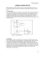
Page 175: ...es The on prox prox closest to the print engine should be set so when the unwind motor turns on It has enough room to ramp up to speed before the printer pulls the roller to the end of the slot This was set at 1 31 from the top of the slot closest to the printer at the factory The off prox should be set far enough apart so both prox switches are not on at the same time This spacing is factory set ...

Page 176: ...iner around the dancer tighten the spring on the backside of the faceplate so the dancer is just held against the stop If the tension is too tight the dancer may not move when the rewind diameter gets too big To tighten the spring loosen the setscrew on the lock collar that supports the spring anchor and rotate When the right tension is achieved re tighten the setscrew It will be important to obse...

Page 177: ......

Page 178: ......

Page 179: ......

Page 180: ......

Page 181: ......

Page 182: ......

Page 183: ......

Page 184: ......

Page 185: ......

Page 186: ......

Page 187: ......

Reviews: