CTI Products, Inc. SLM SiteLync
TM
User Guide
Setup and Operation 7
S
TEP
3. M
AKING
E
LECTRICAL
C
ONNECTIONS
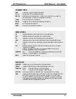
LonWorks Network Connection (NET)
Connect the LonWorks twisted pair channel to the SLM module via the 2
terminal NET connector. This connection is non-polarity sensitive.
Telephone Line Connection (PSTN, ISDN, or CELL)
Connect the telephone service line to the PSTN (for SLM/IM), ISDN (for
SLM/IS), or CELL (for SLM/CL) connector. An RJ11 is provided on the
SLM/IM and SLM/CL models. An RJ45 is provided on the SLM/IS model.
Input Power Connection
Power input is applied to the SLM module via the 3 terminal connector. The
terminals labeled ‘L1’ and ‘L2’ are used for the mains input. SLM units with
power input rating of 10-35 volts AC/DC are polarity insensitive. The terminal
marked with the ground symbol should be connected to protective earth ground.
For SLM units with power input rating of 100-240 VAC that are permanently
connected, a readily accessible disconnect device must be incorporated in the
fixed wiring. For those connected with a pluggable device, the socket-outlet
must be installed near the SLM and must be easily accessible.
Apply power to the SLM SiteLync network modem only after all other
connections have been made.
After power is applied, the PWR indicator should come on. Also, the SERVICE
indicator should come on for approximately 6 seconds. After the SERVICE
indicator goes off, the SLM is ready for use.
S
TEP
4. C
ONFIGURING THE
SLM S
ITE
L
YNC
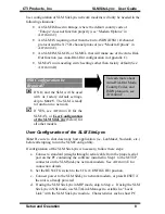
Most typical applications (where a host computer is used to dial into multiple
remote sites containing SLM/IM, SLM/IS, or SLM/CL modules) can make use of
the factory default configuration of the SLM SiteLync (as follows):
•
All models : RUN mode
•
All models : Auto-answer enabled
•
All models : Auto-Dial-Out mode : disabled
•
SLM/IM (EU) : Country code = Europe
•
SLM/IS (EU) : D channel protocol = Euro-ISDN (DSS1)
B channel protocol = X.75


