CTD CM325R Instruction Bulletin & Maintenance Manual Download Page 11

Hand Operated Machines and Cutting Speed:

The blade is rotating at approximately 3700 RPM.  When moving the blade through the material, the blade must 

NEVER

be allowed to


dwell in the work.  If fine finishes are required:

1.  Use a sharp blade.  

Do Not Force the Cutting Action, 

causing the motor to stall.

2.  Use a 

constant, even pressure

 when cutting through material.

Spring Return:

Each sawhead is equipped with a drawbar return spring.  The function of the spring is to return the sawhead to the
rest position upon release of the handle.  

Do not adjust the spring pressure.

  If the spring breaks, 

Replace It

Immediately!


Make sure spring is attached properly (see Diagram “D” on Page No. 8) and 

Never use a hand

operated machine without the return spring in place.

Clamping and Work Slippage:

The work must never be allowed to move or vibrate as it is being cut.  When the work is positioned against a stop,
it 

must be clamped

 either by hand holding or by pneumatic air clamps.  

Never allow unclamped work between

the  blade  and  the  stop,  as  the  blade  can  grab  the  material  and  throw  it,  thereby  causing  damage  to  the
blade, the machine, and possibly harming the operator.

CTD offers both Horizontal and Vertical Clamps.  The Horizontal Clamp pushes the material backwards against the
rear fence and is mounted in the keyways of the base.  A Vertical Clamp holds the material down, against the table base, and
is mounted through and on top of the fence bracket.  Both clamps are offered as optional extras and are highly recommended.
If you purchased your machine with an Air Downfeed of the saw,  the clamps are actuated prior to activating saw head  by
depressing the Foot Valve.  An Anti-Tie Down, Two Hand Control drives down the sawhead.  If clamps are purchased using
a hand operated machine, then the clamps will move into position by pulling the saw head down slightly.  This releases the
Automatic Valve (AV) to supply air to the clamps.  

Be careful not to overtighten clamp cylinder bracket

 on the

cylinder.  This will cause irregular function of the cylinder.

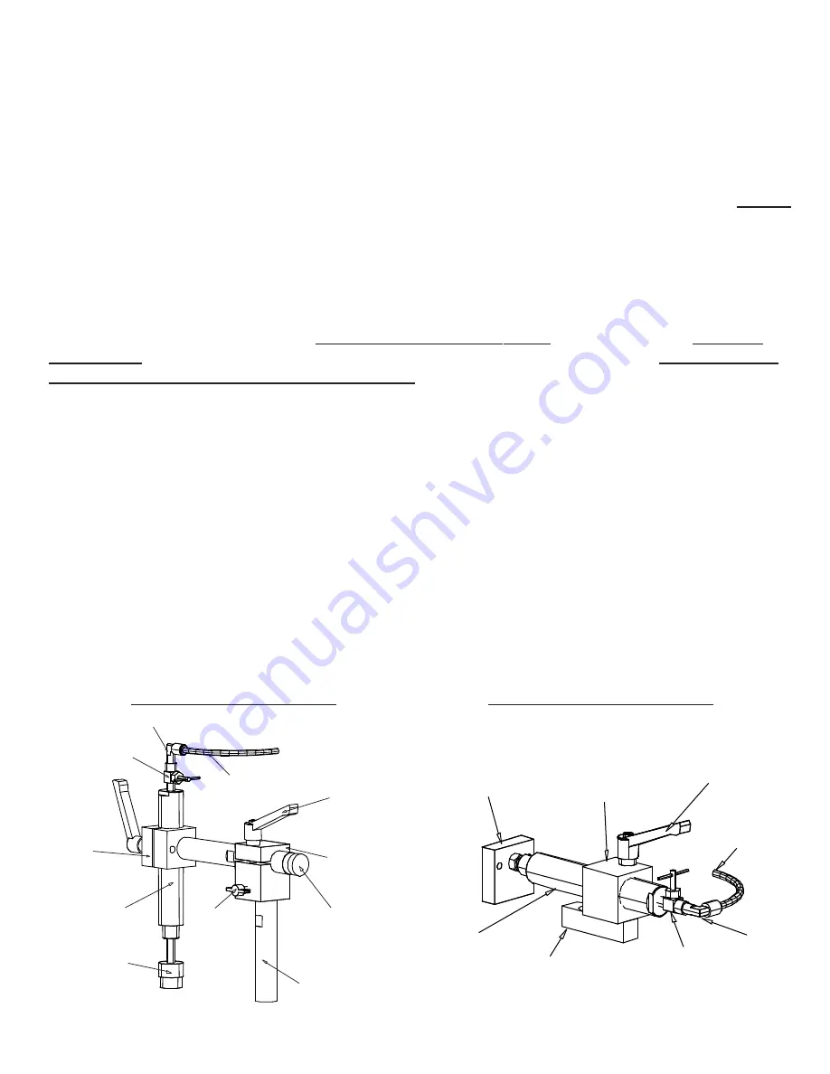
                    200R Vertical Clamp Assembly

200R Horizontal Clamp Assembly

-9-

1/4” elbow fitting

B3P61

shut off

valve

200M22

vert. cyl.

brkt.

2B3P20

3” stroke

air cyl.

2B3P20C

vert. clamp

pad

200BIP22

wing nut

VC

1/4” red polyflo line

200B7P19

adjustable

lock handle

200M21

vert. clamp
adjustment

brkt.

200M20B

horiz. bar adj.

for  vert. clamp

200M20C

vert. clamp

support bar

2BM28

horiz. clamp

pad

200B3P21

3” stroke

air cyl.

200M27

horiz. clamp

key

B3P61

shut off

valve

1/4” elbow fitting

1/4” red polyflo line

200B7P19

adjustable

lock handle

200M22

vert. cyl.

brkt.

4. Turn mitre locking handle to center position, and the spring loaded pin & handle will automatically engage into

preset angle settings.  The preset angle settings are 45

°

, 30

°

, 22 ½

°

, 15

°

, 0

°

 on both sides of the centerline or zero

point.  

Do not let the spring loaded mitre locking pin & handle engage in several degree settings as

you rotate the mitre base disc.  This will cause excess wear on preset angle settings.

5. For all angles that are not preset, follow instructions under #1 to lock handle in the open position.

Simply align degree quadrant on disc with zero mark on base and tighten down intermediate mitre lock handle
located in base.

Summary of Contents for CM325R

Page 1: ...S M25R F255R F255RHC M25RHC CM325R 05 2016 CTD MACHINES 2382 E 48th Street Vernon CA 90058 Tel 213 689 4455 FAX 213 689 1255 World Wide Web http www ctdsaw com e mail ctdsaw ctdsaw com CTD MODEL NO CT...

Page 2: ...h x 4 101mm Wide 3 1 2 89mm High x 4 101mm Wide 45 Mitre 3 1 4 82mm High x 5 127mm Wide Cutting Capacity with fences set at centerline 3 1 2 89mm High x 3 1 2 89mm Wide 45 Mitre 2 1 2 64mm High x 3 1...

Page 3: ...Support Tables and Measuring Gages Standard Machine The standard model has been completely assembled Fences are set at the centerline of the blade see Diagram D on Page No 5 Adjust fences forward if...

Page 4: ...puller p n 200M320 off puller screw and bushing through large hole on slot Remove four machine nuts on Blade Guard Cover 200F250L or R The entire Lower Blade Guard Cover Assembly p n 200E250L or R com...

Page 5: ...attach any additional guarding to the blade guard or table base if the cutting application causes unsafe blade exposure This label is attached to the blade guard Never put hand or fingers near or unde...

Page 6: ...HIS MAY CAUSE SEVERE DAMAGE AND DANGER Consult the factory if any changes are needed Bring power lines to the top of the Manual Overload Starter or Magnetic Starter Use dust proof connectors if availa...

Page 7: ...machine weekly for proper maintenance 11 Keep work area clean Cluttered areas benches and slippery floors invite accidents 12 Avoid dangerous environments Keep work area well illuminated 13 Wear ear p...

Page 8: ...WiringDiagrams...

Page 9: ......

Page 10: ...sure mitre lock down bolt located in the center of the pivot bracket see Diagram D E is loosened 3 To lock in at preset angles rotate sawhead and disc near the desired angle aligning with zero mark on...

Page 11: ...sandarehighlyrecommended If you purchased your machine with anAir Downfeed of the saw the clamps are actuated prior to activating saw head by depressingtheFootValve AnAnti TieDown TwoHandControldrives...

Page 12: ...modifiedblade for best results Consult factory Never use a wood blade to cut aluminum as it will chip and fracture the carbide tips of the blade CuttingAluminum Aswithcuttinganymaterial itisimportantt...

Page 13: ...ured increments The majority of the lubricant then dissipates with the heat of the cutting action Chips coming off the blade are hot and dry and are more easily collected See specific instructions inc...

Page 14: ...tilTwo Hand activation The system will not allow unclamped material to be cut The two hand buttons must be depressed at the same time for the saw head to travel downwards The system operates first by...

Page 15: ...ir Feed 1 200M82 Cylinder Clevis 1 200M84 3Way Valve Bracket 1 200M87 Power Feed Cylinder Support Bar 1 200M86A Rotating Cross Bar for Cylinder 1 B3P86 S1 Shuttle Valve 1 B3P51 FV 3 Way Normally Close...

Page 16: ...d into the blue 1 4 inlet air line at the back of the machine FR AnAirFilter Regulatorisinstalledaheadoftheairinlettothemachine Thissystemhelpspreventforeignmaterialfrom enteringthesystem Italsoprovid...

Page 17: ...bly are constructed using preloaded belleville springs These springs eliminate the need for adjustments of bearings and also greatly increase the life of thebearings Allaircylindersare lubeforlife Gen...

Page 18: ...anually rotate top base to desired degree setting aligning angle mark with zero block 45 and 90 stops are provided 3 Tighten lock down bolt If you desire to mitre beyond 45 to the right then 45 stop m...

Page 19: ...press or pulley puller H Press off slinger and bearing from spindle I Press new bearing on to spindle making sure spindle is square to the bore J Replace slinger as above making sure scored lines mat...

Page 20: ...front Belt guard is on right side blade guard is on left side No Description Part No CM325R SPINDLE ASSEMBLY 1 Spindle Right Hand 30BM02R Spindle Left Hand 30BM02L 2 Flange 30BM03 3 Slinger 30BM04 4...

Page 21: ...19 LEFT OPPOSITE 200 SERIES RIGHT SAW ASSEMBLY...

Page 22: ...L 12 Blade Guard Cover Left 200F250R 12 Blade Guard Cover Right 200A26L 12 Main Blade Guard Left 200A26R 12 Main Blade Guard Right 200E250L R Cover Lower Blade Guard Assy with Link Puller L R 200A270L...

Page 23: ...21 200 Series Right Blade Guard Assy Left Opposite REAR VIEW...

Page 24: ...22 M25R Base Assembly Exploded View Top View Additional Parts 250E01 M25R Base Disc Assy 200E07 Fence and Bracket with fasteners...

Page 25: ...23 F255R Base and Floor Stand Exploded View Additional Parts 25E01 F255 Base Assy 200E07 Fence and Bracket with fasteners...

Page 26: ...24 Air Feed System Exploded View...

Page 27: ...25 CM325R Left Saw Assembly Right Opposite...

Page 28: ...iew Additional Parts 300E260L R Blade Guard Assy Complete Lt or Rt 300A26 L R Main Blade Guard Casting Lt or Rt 300F250L R Cover Main Blade Guard Left or Right 200A270L R Lower Blade Guard Assy w pin...

Page 29: ...27 CM325R Left Base Assy Right Opposite...

Page 30: ...M25HC Base Assembly Exploded View 28...

Page 31: ...200HC Series Blade Guard Assembly 29...

Page 32: ...cellaneous Parts 2D7SR Right to Left Measuring Tape 2D7SL Left to Right Measuring Tape 10P01 Soluble Oil one gallon can B5P01 Single Phase Toggle Switch B5P02 Three Phase Toggle Switch 200BE38 Stop As...

Page 33: ...Notes...

Page 34: ...ise shallnotinanyway include consequential damages or costs of removing or re installingtheproducts All parts and machines are shipped F O B CTD LosAngeles CAPlant CTD MACHINES 2382 E 48th Street Vern...

Reviews: