background image

Crystal Vision 


Using the front control panel 

AVDELAY 3G User Manual R1.11 

25


09/08/2016 


Rotary control – shaft encoder used to select options or variable data  


Note: 

Please refer to the Crystal Vision Control Panel manual for details of the Panel Setup, Lock Panel and 
Diagnostic menus. 

Selecting a AVDELAY 3G 

To select a particular card in a frame, press the DEVICE key to go to the Device menu. 

Note: 

There may be a delay whilst the frame is interrogated during which time the ‘No cards Found’ could be 
displayed. 

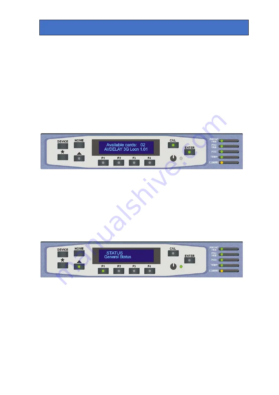
The top line of the display will show ‘Available Cards X’, where X is the number of cards that 
have responded so far to the polling request. 


The available cards menu 

 
Rotate the shaft encoder and the bottom row will display the successfully polled cards by 
name and location or slot number. 

In the example above, the card displayed is located in the first frame in slot number 1. 

When the desired card is selected press the ENTER key to access that card’s HOME menu. 
The message shows that an AVDELAY 3G has been selected. 


The AVDELAY 3G home menu 


Updating the display 

The values displayed on an active front panel are only updated when an adjustment is made 
and when changing menu level. If changes occur through the use of card edge controls or 
other remote control, the text displayed on the active front panel will not be updated 
immediately. If necessary, use the upward arrow to leave and then re-enter a menu to update 
the display. 

Summary of Contents for Indigo AVDELAY 3G

Page 1: ...3G HD SD audio video delay Crystal Vision Ltd Lion Technology Park Station Road East Whittlesford Cambridge CB22 4WL England Tel 44 0 1223 497049 Fax 44 0 1223 497059 sales crystalvision tv www crysta...

Page 2: ...module connections with RM62 8 2 3 General Purpose Interface GPI 9 3 Card edge operation 14 3 1 Card edge controls 14 3 2 Card edge buttons 14 3 3 Card edge rotary control 14 3 4 Reading card edge LE...

Page 3: ...Video control menu 29 Audio controls 29 Preset controls 31 GPO Alarms menu 32 5 Statesman 34 5 1 Statesman introduction 34 5 2 Statesman operation 34 Status 35 Video Control 35 Audio controls 36 Audi...

Page 4: ...wo select buttons a shaft encoder and a display allows you to instinctively and quickly locate any option from menus structured in the most logical way possible Control can additionally be from an act...

Page 5: ...dio delay settings or can bypass the delay completely Flexible adjustments allow you to get the audio and video sync just right with the video delay adjustable in seconds and frames and the four audio...

Page 6: ...dant on the video format The preset delays will also be limited to the maximum delay for any given video format The following table lists the maximum delay for any given video format Video format Maxi...

Page 7: ...for alarm indication and may have assigned any of the 21 video and audio alarms Any number of alarms may be assigned to the GPI output video missing and input groups missing will assert an alarm immed...

Page 8: ...the frame and are included for diagnostic purposes only Note The two potentiometers have been factory set and should not require further adjustments Engineering link and LEDs PL8 sets the AVDELAY 3Gs...

Page 9: ...up to two single height modules All modules can be plugged in and removed while the frame is powered without damage Note For details of fitting rear connectors please refer to the appropriate frame m...

Page 10: ...arm table Alarm condition No alarm As supplied each GPI output has a 270 resistor in series with its output This allows for an external LED to be driven connected to a DC voltage of 5V Each General Pu...

Page 11: ...ce on Group 1 Channel 3 4 Silence on Group 2 Channel 1 2 Silence on Group 2 Channel 3 4 Silence on Group 3 Channel 1 2 Silence on Group 3 Channel 3 4 Silence on Group 4 Channel 1 2 Silence on Group 4...

Page 12: ...5 16 5 17 5 25 5 10 6 11 6 3 8 7 9 7 18 7 26 7 19 8 20 8 4 7 7 16 7 17 7 25 7 10 8 11 8 5 5 5 6 5 15 5 24 5 1 6 2 6 6 4 5 14 5 13 5 23 5 3 6 4 6 7 5 7 6 7 15 7 24 7 1 8 2 8 8 4 7 14 7 13 7 23 7 3 8 4...

Page 13: ...Remote 4 are 26 way high density D Type male plugs and frame ground is pin 6 in each case and 5V 500mA is pin 15 on Remote 2 Note The 5V output is protected by self resetting thermal fuses which limit...

Page 14: ...1 8 1 9 1 18 1 26 1 19 2 20 2 2 7 1 16 1 17 1 25 1 10 2 11 2 Table shows pin number remote number Note Remote 1 26 way high density D Type female socket Frame ground is pin 2 and 5V 500mA is pin 1 Re...

Page 15: ...menu level or cancel a selection ENTER Select Action Push to select a menu and to action and confirm a change 3 3 Card edge rotary control The board edge rotary encoder is used to navigate through the...

Page 16: ...up 2 not present G3 Yellow Audio Group 3 present Audio Group 3 not present G4 Yellow Audio Group 4 present Audio Group 4 not present Yellow GPO6 Yellow GPO6 active low GPO6 inactive high 3 5 Navigatin...

Page 17: ...ual R1 11 16 09 08 2016 3 6 Card edge configuration Menu tree AVDELAY 3G Board edge menu structure Tip To reach the top menu push the button repeatedly until a top menu is reached Rotate the SCROLL AD...

Page 18: ...IP address AVDELAY 3G IP address Note the Ethernet connection is available on board and is only used when updating the board software Input Groups Press ENTER and rotate SCROLL ADJ Audio Group 1 Inpu...

Page 19: ...elay in frames control Press ENTER and rotate SCROLL ADJ to vary 0 30 Video delay in seconds Rotate the SCROLL ADJ control to show the video delay in seconds Press ENTER and rotate SCROLL ADJ to vary...

Page 20: ...2 delay select Press ENTER and rotate SCROLL ADJ Channel 1 delay group select Rotate the SCROLL ADJ control to show the Group 2 Ch1 control Press ENTER and rotate SCROLL ADJ to select 1 2 3 4 By Chann...

Page 21: ...ay 1 time in frames Rotate the SCROLL ADJ control to show the Delay 1 frame control Press ENTER and rotate SCROLL ADJ to select 0 30 frames Delay 1 time in seconds Rotate the SCROLL ADJ control to sho...

Page 22: ...lled either from the board control active front panel Statesman or through the use of external GPIs Presets store the board setup data including operating mode card status The presets are numbered 1 1...

Page 23: ...cted Preset 1 GPI Enable Disabled GPO6 Alarms Un selected Silence delay 0 seconds GPI Alarms menu The GPO6 output is reserved for alarm indication and may have assigned any of the 21 video and audio a...

Page 24: ...roup 2 Group 3 Group 4 Press ENTER and rotate SCROLL ADJ to select On Off Input audio group 4 missing Group1 Ch1 2 silent Rotate the SCROLL ADJ control to show the de embedder channel silent alarms Gr...

Page 25: ...or configuration press the CAL key once A second press of the CAL key will return to Statesman control The control panel will display the name of the card that first responds to the polling request t...

Page 26: ...far to the polling request The available cards menu Rotate the shaft encoder and the bottom row will display the successfully polled cards by name and location or slot number In the example above the...

Page 27: ...further menus are available The top level menus are Status General Status Input Group Presence De Embedder Audio Silence Video Control Video Mode Video Timing Audio Control Delay Select Preset Control...

Page 28: ...Crystal Vision Using the front control panel AVDELAY 3G User Manual R1 11 27 09 08 2016 Active control panel menus Note Function key LEDs are illuminated when active...

Page 29: ...ress Note the Ethernet connection is available on board and is only used when updating the board software Input Groups Rotate the shaft control and press F1 Input Group 1 audio Rotate the shaft contro...

Page 30: ...onds Press F1 and rotate the shaft control to adjust 0 10 Input mode The AVDELAY 3G has the option of either receiving an optical input or transmitting an optical output once the necessary SPF optical...

Page 31: ...rotate the shaft control to select Channel 1 Channel 2 Channel 3 Channel 4 Press F1 to fix and enter delay selection and rotate shaft control to select delay Delay 1 Selected Delay 2 Selected Delay 3...

Page 32: ...the chosen location 1 16 Press F1 to enter menu and press F3 to save the current configuration Press F4 to recall a previously saved board configuration Preset location 16 Preset menu and factory rese...

Page 33: ...ry reset will erase all user stored presets Parameter Default value Video delay controls 0 Video input select BNC Audio Controls Delay 1 Audio delay 0 Selected Preset 1 GPI Enable Disabled GPO6 Alarms...

Page 34: ...roup 3 Group 4 Press F1 and rotate shaft control to select On Off Input audio group 4 missing De embedder Grp1 Ch1 2 silent Rotate the shaft control to show the de embedder channel silent alarms Group...

Page 35: ...anel An active panel or REMIND remote control panel must be fitted to allow Statesman control 5 2 Statesman operation The initial view will show an Explorer style view of the connected frames and modu...

Page 36: ...t is used where more information is required than can be inferred by a simple LED such as video standards Status monitoring Input Video and audio status Input present is indicated by a simulated LED g...

Page 37: ...using three preset buttons will be similarly affected by the video format See the table in the Delay section of the Introduction for maximum delay per video format Note The maximum delay will automati...

Page 38: ...Manual R1 11 37 09 08 2016 Audio input Audio delay The four audio delays have their own individual sets of adjustments Alongside the slider controls are three preset buttons which can be used to apply...

Page 39: ...press enter This will write the current settings into this location Note If the selected location contains previously saved setting information it will be over written by the new setting data When pa...

Page 40: ...of alarms may be assigned to the GPI output video missing and input groups missing will assert an alarm immediately whereas the silence alarms can be assigned a delay time to delay the time after whic...

Page 41: ...f the monitor supplies is out of specification Yellow HD Yellow Video input standard is HD High Definition Input not present SD Yellow Video input standard is SD Standard Definition G1 Yellow Audio Gr...

Page 42: ...stability is within normal limits The card no longer responds to card edge or front panel control Check that the card is seated correctly and that the Power OK LEDs are lit Check any active control p...

Page 43: ...80p 50 59 94 1080i 50 59 94 720p 50 59 94 PAL NTSC Input format auto selected Return loss 50Mhz to 1 5GHz 15dB 1 5GHz to 2 97GHz 10dB Audio Four groups of embedded audio Outputs Video Serial output 27...

Page 44: ...lectrically Open collector transistors 30V 270Ohm current limit resistors Pulled up to 5V through 7kOhm Input fail output Type Delay Then Blue Control Local Intuitive board edge interface with two sel...

Reviews: