


Cryo-con Model 24C
Basic Setup and Operation
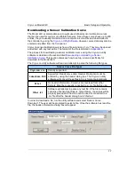
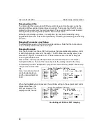
When the tuning process is successfully completed, a status of Complete will be
indicated and the values of P, I and D will be updated with the generated values. To
accept these values and save them as the loop PID coefficients, select the Save&Exit
field. To reject the values and exit, press the
ESC
key.
Autotune may always be aborted by pressing the
ESC
key.
An unsuccessful autotune is indicated by one of the following status lines:
1. Failed. This indicates that the process model did not converge or that PID
values could not be generated from the result.
2. Aborted. Autotune was aborted by user intervention such as pressing the
Stop key.
Temperature Ramping
Operation
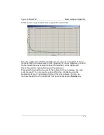
The Model 24C performs a temperature ramp function using a specified ramp rate
and target setpoint. Once placed in a ramping control mode, a ramp is initiated by
changing the setpoint. The unit then progresses to the new setpoint at the selected
ramp rate. Upon reaching the new setpoint, ramp mode is terminated and standard
PID type regulation will be performed.
Ramping may be independently performed on control loop.
The procedure for temperature ramping is as follows:
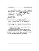
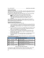
1. Set the Ramp Rate in the Heater Configuration Menu. This parameter
specifies the ramp rate in Units Per Minute, where Units are the
measurement units of the input channel controlling the heater. For
example, if the input channel units are Kelvin, the ramp rate is in K/min.
2. Select the ramping Control Mode, RampP.
3. Press CONTROL. Now, the controller will begin temperature regulation at
the current setpoint.
4. Enter a new setpoint. The controller will enter ramping mode, and ramp
to the target setpoint at the specified rate.
5. When the new setpoint is reached, ramping mode terminates and
temperature regulation will begin at the new setpoint.
6. Entry of a different setpoint will initiate another ramp.
As a variation on the above procedure:
1. The controller may be regulating temperature in any available control
mode. This mode can be changed to a ramping mode without exiting the
control loop. This will not result in a ‘glitch’ in heater output power.
2. Once a ramp mode is selected, ramping is performed, as above, by
changing the setpoint.
The current status of the ramp function may be seen on the Operate Screen. When a
ramp is active, the word RMP will appear in the control loop status displays. It may
also be queried via any of the remote ports using the LOOP 1:RAMP? Command.
85


