


Cryo-con Model 24C
Basic Setup and Operation
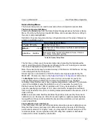
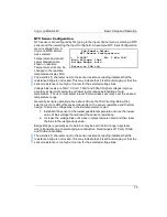
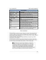
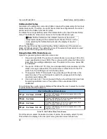
The Sensor Name can be any string, up to 15 characters, that helps identify the
sensor. The Sensor Type, Multiplier and Unit fields affect how the instrument is
configured, so they must be correctly set or unexpected results will be obtained.
Sensor
Type
Multiplier
Units
Example
Cernox™
ACR
-1.0
LogOhms
CX1030E1.crv
Ruthenium-Oxide
ACR
-1.0
LogOhms
LSRX102.crv
Thermistors
ACR
-1.0
LogOhms
LSRX102.crv
Rhodium-Iron 27
PTC100
1.0
Ohms
rhfe27.crv
CLTS-2B
CLTS
1
Ohms
Germanium
ACR
-1.0
LogOhms
LSRX102.crv
Carbon Glass
ACR
-1.0
LogOhms
LSRX102.crv
Silicon diode
Diode
-1.0
Volts
s900diode.crv
Carbon Ceramic
ACR
-1.0
LogOhms
LSRX102.crv
Platinum 100
PTC100
1.0
Ohms
PT100385.crv
Platinum 1K
PTC1K
1.0
Ohms
PT1K385.crv
GaAlAs diode
Diode
-1.0
Volts
s900diode.crv
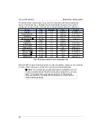
Table 29: Recommended Sensor Configuration Data
Note that NTC resistor data is generally in units of LogOhms. However, it can also be
in units of Ohms. Be sure to check the curve data for reasonableness.
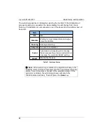
i
Note:
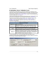
One simple way to generate a sensor calibration curve is
to open a similar sensor file with a text editor and paste in your own
data. The example files in the above table are for that purpose.
They are located in the Model 24C sub-directory of the Cryo-con
utility software package.
78


