Page 18
IQ-USM 810
IQ Digital Processor / Digital Mixer
IQ-USM 810
Reference Manual
High-Pass Equalization Filter
Description: This filter combines the functions of the
parametric equalization filter to boost or cut a rela-
tively narrow frequency band with a high-pass filter to
roll of the frequencies below the center frequency.** It
is commonly used to create a B
6
(6th-order
Butterworth) response in a vented loudspeaker enclo-
sure.
Passband Gain:
Sets the amount of boost or cut for the
filter. Control range is +24 dB to –24 dB in
1
/
2
-dB steps.
Frequency:
Sets the center frequency of the filter. Con-
trol range is 20 Hz to 20 kHz in 1-Hz increments.
Octave Bandwidth:
Sets the width and slope, or “Q” of
the filter (see Figure 4.1). The lower the Q, the wider the
filter and the better the transient response and visa
versa. Control range is from 0.0416 (
1
/
24
octave) to
6.667 (6
2
/
3
octave) in 0.0416 (
1
/
24
-octave) increments.
CAUTION: Avoid excessive Qs.*
Low-Pass Shelving Equalization Filter
Description: This filter boosts or cuts low frequencies
by the specified amount of gain. When used to cut
rather than boost, the filter acts like a high-pass filter
rather than a low-pass filter. It has a fixed 1st-order
slope (6 dB/octave).
Passband Gain:
Sets the amount of boost or cut for the
filter. Control range is +24 dB to –24 dB in
1
/
2
-dB steps.
Frequency:
Sets the –3-dB corner frequency relative
to the boosted pass band. Control range is 20 Hz to 20
kHz in 1-Hz increments.
High-Pass Shelving Equalization Filter
Description: This filter boosts or cuts high frequen-
cies by the specified amount of gain. When used to
cut rather than boost, the filter acts like a low-pass
rather than a high-pass filter. It has a fixed 1st-order
slope (6 dB/octave). It is commonly used to com-
pensate for the natural high-frequency roll-off of
constant directivity horns.
Passband Gain:
Sets the amount of boost or cut for the
filter. Control range is +24 dB to –24 dB in
1
/
2
-dB steps.
Frequency:
Sets the +3-dB corner frequency relative to
the boosted pass band. Control range is 20 Hz to 20
kHz in 1-Hz increments.
All-Pass Filter
Description:This filter lets the user perform phase equal-
ization without affecting the frequency response.
4.3.2 Input Processing Delay
A delay can be added to any of the eight input channels
in order to time-equalize the various input signals. Delay
is displayed in IQ for Windows software in time, feet,
and meters. Control range is from 0 to 100 milliseconds
in 20-microsecond steps.
4.3.3 Input Gate
The Input Gate feature allows signals above a certain
level to pass and attenuates lower level signals. When
“open,” the Input Gate passes the input signal un-
attenuated. When “closed,” it attenuates the input signal
by an amount specified with the Depth control. There are
eight parameters which control this feature:
•
•
•
•
•
On/Off:
turns this feature on or off.
•
•
•
•
• Depth:
Depth:
Depth:
Depth:
Depth: sets the “closed” gain of the Gate. Control
range is from –100 dB to 0 dB in
1
/
2
-dB steps.
•
•
•
•
• Threshold:
Threshold:
Threshold:
Threshold:
Threshold: specifies the peak signal level (after
side-chain processing) above which the gate will
open. Control range is from –80 to +20 dB in
1
/
2
-dB
steps.
•
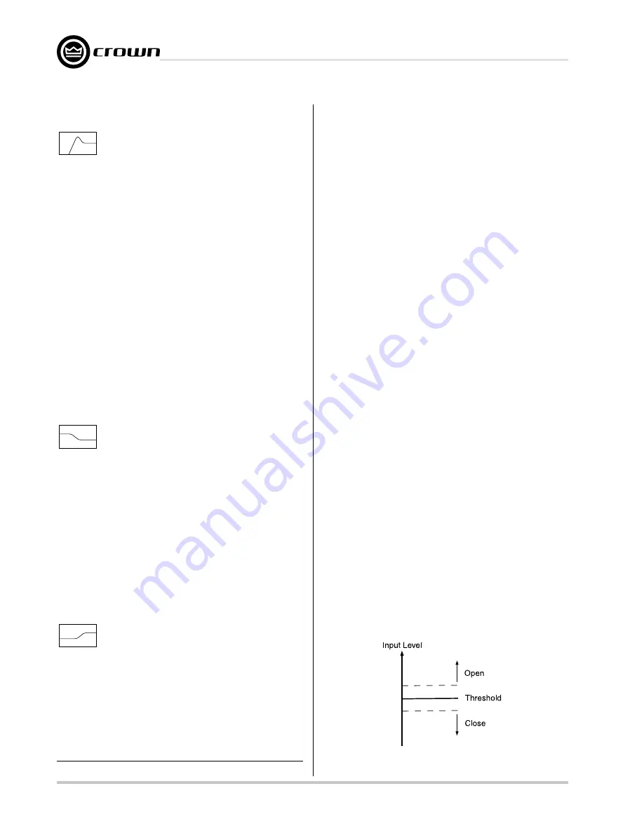
Hysteresis:
sets a range in dB above and below
the Threshold which seperates the levels at which
the Input Gate opens and closes (Figure 4.2). The
input signal must reach a level above the Thresh-
old plus Hysteresis to open. Once opened, the in-
put signal must reach a level below the Threshold
minus Hysteresis to close. Control range is from 0
dB to 12 dB in
1
/
2
-dB steps.
* High Q filters with gain greater than unity can cause unwanted ringing. This
is true for both digital and analog filters.
Figure 4.2 Hysteresis


