


41
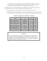
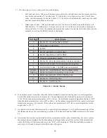
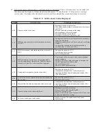
7) Start the boiler using the lighting instructions on page 39. After the boiler is powered up, it should go through
the following sequence.
Sequence Display
Meaning
1
U.125
or Blank
Checking internal software (power-up only)
2
0.SWT
Boiler in standby.
SWT
= Supply Water Temp. No call for heat.
(After call for heat from heating thermostat)
3
A.SWT
Self-Check on Start-up
4
5.SWT
Blower and circulator on. Checking for adequate air flow.
5
1.SWT
Prepurge
6
2.SWT
Trial for ignition
7
3.SWT
Flame established. Boiler responding to a call for heat.
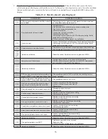
8) Upon initial start-up, the gas train will be filled with air. Even if the gas line has been completely purged of air,
it may take several tries for ignition before a flame is established. If more than 5 tries for ignition are needed,
it will be necessary to press the reset button to restart the boiler. Once a flame has been established for the first
time, subsequent calls for burner operation should result in a flame on the first try.
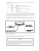
9) Inspect the flame visible through the window. On high fire the flame should be stable and mostly blue
(Fig.10.1). No yellow tipping should be present; however, intermittent flecks of yellow and orange in the flame
are normal.
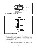
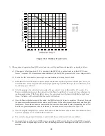
10) Check the inlet pressure and adjust if necessary. Verify that the inlet pressure is between the upper and lower
limits shown on the rating plate with all gas appliances on and off.
Figure 10.1: BWC Burner
WARNING
THE CORRECT OUTLET PRESSURE FOR THE GAS VALVE HAS BEEN FACTORY SET
AND REQUIRES NO FIELD ADJUSTMENT. THIS SETTING IS SATISFACTORY FOR
BOTH NATURAL GAS AND PROPANE. ATTEMPTING TO ADJUST THE OUTLET PRES
-
SURE MAY RESULT IN DAMAGE TO THE GAS VALVE AND CAUSE PROPERTY DAM-
AGE, PERSONAL INJURY OR LOSS OF LIFE.
Summary of Contents for BIMINI BWC225
Page 2: ......
Page 22: ...20 PAGE INTENTIONALLY LEFT BLANK ...
Page 23: ...21 PAGE INTENTIONALLY LEFT BLANK ...
Page 24: ...22 PAGE INTENTIONALLY LEFT BLANK ...
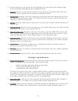
Page 29: ...Figure 8 3 Piping Method 1 Heat Indirect Water Heater 27 ...
Page 37: ...Figure 9 1 Wiring Connections Diagram 35 ...
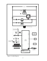
Page 38: ...Figure 9 2 Ladder Diagram 36 ...
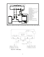
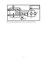
Page 39: ...Figure 9 3 Wiring of Isolation Relay for Control of Two Heating Circulators 37 ...
Page 56: ...54 PAGE INTENTIONALLY LEFT BLANK ...
Page 60: ...58 ...
Page 61: ...59 ...
Page 62: ...60 ...
Page 63: ...61 Gas Train Assembly Honeywell Valve ...
Page 64: ...Gas Train Assembly Dungs Valve 62 ...
Page 66: ...64 ...
Page 68: ...66 ...
Page 69: ...67 ...
Page 70: ...68 ...
Page 72: ......


