


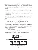


X Start-up and Checkout
Use the following procedure for initial start-up of the boiler:
1) If not already done, flush the system to remove sediment, flux, and traces of boiler additives. This should be
done with the boiler isolated from the system.
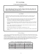
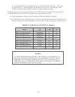
2) Fill the boiler and hydronic system with water meeting the following requirements:
pH between 6.5 and 8.5
Total Solids less than 2500 PPM
Hardness less than 120 PPM (7 Grains/Gallon)
Pressurize the system to at least 12 psi at the boiler
3) Check all new piping for leaks and purge piping sections that are filled with air. See the
National Fuel Gas
Code
for additional information on testing and purging gas lines.
4) Vent system must be complete and free of obstructions before attempting to fire boiler. Make sure that the
silicone cure time called for in the vent assembly instructions has passed before firing boiler.
5) Inspect all line voltage wiring for loose or uninsulated connections.
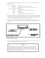
6) Remove the dust cap from the condensate trap (Fig 6.11). Add water to the trap until water runs out the con
-
densate drain. Reinstall the dust cap.
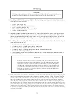
NOTE
SAFE LIGHTING AND OTHER PERFORMANCE CRITERIA WERE MET WITH THE GAS TRAIN
ASSEMBLY PROVIDED ON THE BOILER WHEN THE BOILER UNDERWENT THE TEST
SPECIFIED IN Z21.13.
WARNING
• NEVER ATTEMPT TO FILL A HOT EMPTY BOILER.
38
WARNING
• NEVER USE A FLAME TO CHECK FOR GAS LEAKS.
• MAKE SURE THAT THE AREA AROUND THE BOILER IS CLEAR AND FREE FROM
COMBUSTIBLE MATERIALS, GASOLINE AND OTHER FLAMMABLE VAPORS AND
LIQUIDS
Summary of Contents for BIMINI BWC225
Page 2: ......
Page 22: ...20 PAGE INTENTIONALLY LEFT BLANK ...
Page 23: ...21 PAGE INTENTIONALLY LEFT BLANK ...
Page 24: ...22 PAGE INTENTIONALLY LEFT BLANK ...
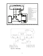
Page 29: ...Figure 8 3 Piping Method 1 Heat Indirect Water Heater 27 ...
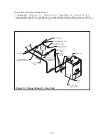
Page 37: ...Figure 9 1 Wiring Connections Diagram 35 ...
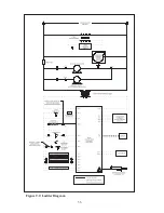
Page 38: ...Figure 9 2 Ladder Diagram 36 ...
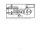
Page 39: ...Figure 9 3 Wiring of Isolation Relay for Control of Two Heating Circulators 37 ...
Page 56: ...54 PAGE INTENTIONALLY LEFT BLANK ...
Page 60: ...58 ...
Page 61: ...59 ...
Page 62: ...60 ...
Page 63: ...61 Gas Train Assembly Honeywell Valve ...
Page 64: ...Gas Train Assembly Dungs Valve 62 ...
Page 66: ...64 ...
Page 68: ...66 ...
Page 69: ...67 ...
Page 70: ...68 ...
Page 72: ......


