background image

Crestron 

TPMC-12


Isys

®

 12” Tilt Touch Screen


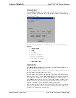
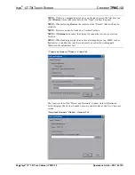
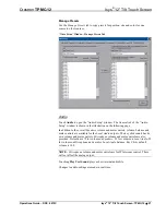
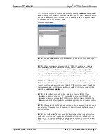
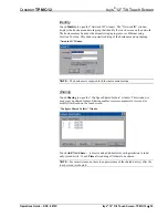
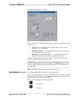
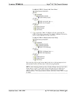
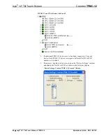
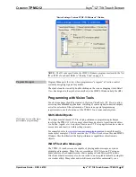
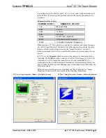
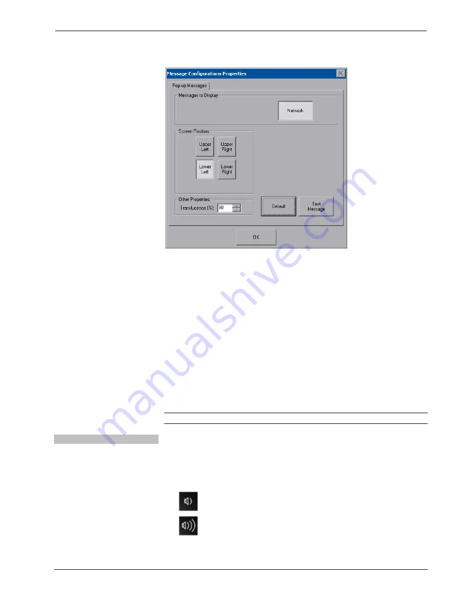
“Message Popup Configuration” Window 


There are three types of 

Network

 popup messages. Following are definitions of each 

message type: 

• 

Connected:

  A green popup message appears when the touch screen is 

connected to the control system.


• 

Checking Connection:

  A yellow popup message appears when the touch 

screen is experiencing network issues. 

• 

Disconnected, Trying to Reconnect…:

  A red popup message appears 

when the touch screen loses connection with the control system. 

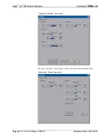
A control for popup message 

Translucence

 is also provided. Translucence ranges 

from 25% to 100%, with a default value of 90%. 

The 

Default

 button restores the original 

Screen Position

 and 

Translucence

 settings, 

as well as enabling display of 

Network

 messages. A 

Test Message

 button lets you 

see the changes to popup message position and translucence. Touch 

Close

 to close 

the popup window. 

NOTE:

  The default value for 

Screen Position

 is 

Lower Left

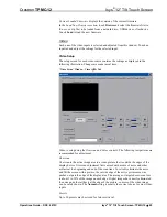
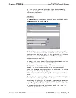
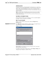
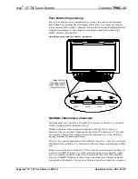
Show Keyboard 

Touch the 

Keyboard

 button to display the on-screen keyboard. 

The on-screen keyboard can be used in an identical manner to a physically connected 
keyboard. It can be used in any of the embedded applications, for example, to enter a 
web address or to enter data into a spreadsheet, etc. 

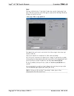
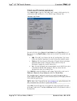
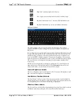
The on-screen keyboard also has a few special keys: 

 Volume 

down 

 Volume 

up 

Operations Guide – DOC. 6675C 

Isys

®

 12” Tilt Touch Screen: TPMC-12  

  37 

Summary of Contents for n TPMC-12

Page 1: ...Crestron TPMC 12 Isys 12 TiltTouchScreen Operations Guide ...

Page 2: ...s Reorient or relocate the receiving antenna Increase the separation between the equipment and receiver Connect the equipment into an outlet on a circuit different from that to which the receiver is connected Consult the dealer or an experienced radio TV technician for help As of the date of manufacture the TPMC 12 has been tested and found to comply with specifications for CE marking and standard...

Page 3: ...uilder 44 Programming with SIMPL Windows 44 Programming with VisionTools 47 Embedded Applications 51 Defaults for Embedded Windows Applications 52 Programming Embedded Windows Applications 53 Uploading and Upgrading 55 Establishing Communication 55 Programs Projects and Firmware 56 Program Checks 56 Restore 56 Operation 57 MediaMarker 57 Security Infrastructure 57 Problem Solving 59 Troubleshootin...

Page 4: ......

Page 5: ...een graphics 800 x 600 resolution DNav dynamic menu objects Full motion video with gamma correction Interactive annotation capability Windows XP Embedded operating system Onboard PC applications for Web browsing streaming media and remote computer access Multi format streaming video and audio Direct screen to screen intercom over IP WAV file audio feedback Built in amplified speaker system and mic...

Page 6: ...n the touch screen environment to create a truly powerful and user friendly interface Integrated Video For presentation preview surveillance or pure entertainment the TPMC 12 provides multiple ways to view video signals from security cameras movies and other sources right on the touch screen Video images can be displayed full screen as well as in a fully scalable window High quality full motion vi...

Page 7: ...wiring distances of up to 450 feet 137 meters the QM input port accepts video signals from composite S video and standard definition component sources along with discrete audio signals from one stereo program source and up to two microphones QuickMedia implementation in this product supports standard definition video only does not support HDTV or high resolution RGB High Speed Connectivity Both Cr...
Page 8: ...s XP Embedded Graphic Engine 24 bit non palette graphics 8 bit alpha channel translucency 16 7 million colors multi mode objects DNav dynamic menu objects dynamic graphics 1 PNG translucency full motion 60 fps animation transition effects color key video windowing remote annotation Embedded PC Applications 2 Microsoft Internet Explore with Adobe Flash plug in Windows Media Player RealPlayer Crestr...

Page 9: ...io Feedback WAV 8 and 16 bit PCM 8 44 1 kHz sampling rates Mono and stereo D A Conversion QM only 24 bit 48 kHz Amplification Mono 5 Watts x 2 Power Requirements Cresnet Power Usage 37 Watts 1 54 Amps 24 Volts DC Default Net ID 4 03 Minimum 2 Series Control System Update File5 6 Version 4 001 1012 or later Environmental Temperature 41 to 113 F 5 to 45 C Humidity 10 to 90 RH non condensing Heat Dis...

Page 10: ...rotected FTP or HTTP server 2 Contact Crestron for a current list of compatible devices and embedded applications To ensure reliable performance new device drivers and applications are available only from Crestron through firmware updates 3 The supported VNC viewer is UltraVNC version 1 0 2 Other VNC viewers may work but are not guaranteed 4 Refer to Identity Code on page 15 for details 5 The late...

Page 11: ...Tilt Touch Screen Physical Description This section provides information on the connections controls and indicators available on your TPMC 12 TPMC 12 Physical View Operations Guide DOC 6675C Isys 12 Tilt Touch Screen TPMC 12 7 ...

Page 12: ... 12 Tilt Touch Screen Crestron TPMC 12 TPMC 12 Overall Dimensions Front View 12 85 in 327 mm 10 43 in 265 mm 12 15 in 309 mm 11 60 in 294 mm 1 8 Isys 12 Tilt Touch Screen TPMC 12 Operations Guide DOC 6675C ...

Page 13: ...on TPMC 12 Isys 12 Tilt Touch Screen TPMC 12 Overall Dimensions Side View 12 40 in 315 mm 10 71 in 272 mm 45O TPMC 12 Connectors 2 4 3 5 6 8 9 7 Operations Guide DOC 6675C Isys 12 Tilt Touch Screen TPMC 12 9 ...

Page 14: ...d lug 4 USB 1 2 3 4 2 USB Type A female USB 2 0 ports for USB keyboard mouse and storage devices 3 5 MEMORY EXPANSION 1 MMC compatible card slot Accepts Multimedia Memory Cards MMC up to 4 GB for memory expansion 3 6 LAN YELLOW GREEN LED GREEN LED PIN 8 PIN 1 1 8 wire RJ 45 with two LED indicators 10BASE T 100BASE TX 1000BASE T Ethernet port Left yellow LED indicates 10 Mbps link status Left green...

Page 15: ... length 500 feet 152 meters for component 750 feet 229 meters for composite S video 9 AUDIO I O6 8 1 8 1 8 wire RJ 45 female bidirectional CAT5 balanced audio port Signal type receives 1 balanced stereo audio signal and transmits 1 balanced stereo audio signal from internal microphone Maximum input level 4 Vrms Maximum output level 2 Vrms Input output impedance 600 Ω Connects to any other Crestron...

Page 16: ... provides component composite or S video balanced input to the touch screen over CAT5 wiring Refer to the following table for connector pinouts PIN WIRE COLORS 568B COMPOSITE S VIDEO COMPONENT 1 WHITE ORANGE Composite Luminance Y 2 ORANGE Composite Luminance Y 3 WHITE GREEN N A Chrominance Pb 4 BLUE N A N A Pr 5 WHITE BLUE N A N A Pr 6 GREEN N A Chrominance Pb 7 WHITE BROWN N A N A N A 8 BROWN N A...

Page 17: ...AT5 Wiring Category 5 CAT5 wiring is a twisted pair cable designed for Ethernet networks These networks operate at speeds of up to 100 Megabits per second Mbps using the 100BASE T standard Crestron takes advantage of this specification for a variety of audio and video applications When using a Crestron wiring solution the CresCAT IM or D wire can carry audio and video signals up to 500 feet 152 me...

Page 18: ... feet The use of lower resolution signals may allow increased cable length but must be tested by the installer with the sources to be used The QM pin assignment is based on the EIA TIA 568B RJ 45 Jack standard NOTE When transmitting S video luminance uses the green video pathway and chrominance uses the red video pathway When transmitting composite video the signal is carried on the blue video pat...

Page 19: ... more details refer to the Crestron Toolbox help file IP ID The IP ID is set within the TPMC 12 s table using Crestron Toolbox For information on setting an IP table refer to the Crestron Toolbox help file The IP IDs of multiple TPMC 12 devices in the same system must be unique When setting the IP ID consider the following The IP ID of each unit must match an IP ID specified in the SIMPL Windows p...

Page 20: ...ser Account Info Window 3 Enter the user account tpmcadmin and the password tpmcadmin and touch Validate NOTE The password is case sensitive After logging in the password can be changed from the Security window Refer to Security which starts on page 18 for more information 4 When the Crestron Debug Output window appears shown in the following diagram select Project Enter Setup Mode to enter the se...

Page 21: ...en during boot up when you see the Preparing to Load Project message Maintain touch until after the countdown when the message will change to Loading Setup Screen The setup menu provides access to all basic functions and parameters It is divided into a top row of setup buttons and Ethernet Standby Hard Button Backlight Misc Controls Screen Brightness Hard Button Feedback and Ethernet Status sectio...

Page 22: ... mode the setup menu will still be available but all setup windows will be disabled i e you will not be able to bring up any setup window via a digital join For more information about Annotation mode refer to About Annotation Mode in the Crestron VisionTools VT Pro e Help file Security The Security button opens the Security Setup window which allows the user to change the username and password of ...

Page 23: ...ormat Remote host name Shareable folder name 2 Map this connection by selecting a drive letter from the Map Drive Letter drop box 3 Enter a user name and password 4 Touch the Remember and reconnect on startup checkbox if so desired 5 Touch OK to enable the new network connection and return to the Network Connections window Once all changes to network connections have been completed touch OK to ret...

Page 24: ...p Window Select Enable for normal Cresnet communication mode and Disable when the touch screen is connected to a control system via Ethernet Communication mode is factory set to Enable The Cresnet network identity number Cresnet ID is displayed in the Cresnet Setup window Cresnet ID is a two digit hexadecimal number The hexadecimal number can range from 03 to FE and must correspond to the Net ID s...

Page 25: ...ere will be a series of crosshairs on the screen starting near the upper left corner Touch the center of the first crosshair to initiate calibration As each new crosshair is touched the next will appear After the upper left crosshairs will appear in the upper center upper right middle left screen center middle right lower left lower center and finally lower right Touch the center of the crosshair ...

Page 26: ...reen Test is touched the test screen will be displayed refer to illustration below This screen allows the user to test the touch screen response at 17 points on the screen Each button on the screen will light when touched Touch Return to exit the test screen Touch Screen Test Window 22 Isys 12 Tilt Touch Screen TPMC 12 Operations Guide DOC 6675C ...

Page 27: ...Firmware window is divided into two sections Current Loaded Project and Load New Project Current Loaded Project displays the name and creation time of the current project In the Load New Project section touch Browse and select the compiled project i e the vtz file to be loaded from a network drive USB device or flash drive then touch Open to show the source file in the Project and Firmware window ...

Page 28: ...s checked the display list cannot be viewed via Crestron Toolbox NOTE When loading a project to an external storage device e g MMC card or flash drive a subdirectory not the root must be used as the working path Otherwise the upload may fail Project and Firmware Window Project Tab The Firmware tab of the Project and Firmware window refer to illustration below displays the Current Loaded Firmware a...

Page 29: ...controls The following test patterns are recommended for adjustment Overscan Overscan is the active image area in a video picture that is outside the edges of the display device Overscan adjustment first came about because of noise and other artifacts at the beginning and end of the scan lines To reliably eliminate the noise and fill the screen with a picture the outside edge of the active picture...

Page 30: ...reaking Up to 255 preset locations are available to store settings for peak and boost In QM systems using auto compensation the touch screen can be set to automatically recall preset values upon receipt of a QM ID by selecting Auto Load on QM ID In order to manually load preset values make sure Auto Load on QM ID is not selected For more information on peak and boost settings refer to the latest r...

Page 31: ...ce and mute controls are available for the Local Audio outputs The key click sound has its own volume and mute controls Microphone volume and mute controls are also provided Defaults are 75 for volume on Speakers 25 for volume on Local Audio 25 for volume on Microphone and zero for Local Audio balance Key Clicks default volume is 100 NOTE Microphone volume and mute controls are for IP Intercom con...

Page 32: ...reen Crestron TPMC 12 Audio Setup Window General Tab The Inputs tab of the Audio Setup window is shown in the illustration below Audio Setup Window Inputs Tab 28 Isys 12 Tilt Touch Screen TPMC 12 Operations Guide DOC 6675C ...

Page 33: ...y select a flash memory card a network drive or a USB drive The Default Frame Template browse button permits you to search for templates For Crestron provided templates choose from the pulldown list Frames created during the annotation session will use a default annotation template file frame prefix and frame output file type Each new frame title will contain the frame prefix followed by a sequent...

Page 34: ...propriate for most Internet sites Low Minimal safeguards and warning prompts are provided Most content is downloaded and run without prompts All active content can run Appropriate for sites you absolutely trust Touch Default to restore the default security settings By default security is set to Medium for Internet and Local Intranet and Low for Trusted Sites The Embedded Apps window also permits y...

Page 35: ...the VNC server when the VNC View application is opened For automatic connection without having to enter the server location and password every time the VNC viewer is opened launch the application and using a USB mouse right click on the VNC viewer window then select Save configuration info as NOTE Refer to the Crestron Web site online help Answer ID 4627 for information on how to set up the VNC vi...

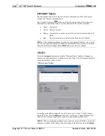
Page 36: ...ds after seeing the change in the Ethernet Status section of the main setup menu before initiating a Save Reboot to save the new settings Adapters Touch the Adapters button to access the Ethernet Setup window Changes are made in real time and there is typically no need to reboot The Ethernet address and mask are displayed on this screen Ethernet Setup Window To configure the Ethernet adapter touch...

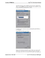
Page 37: ...Connection Window To establish dynamic or static processing select Internet Protocol TCP IP and touch Properties Internet Protocol TCP IP Properties Window Transmission Control Protocol Internet Protocol TCP IP is a set of protocols that defines how to transfer data between two computers TCP monitors and ensures correct transfer of data IP receives the data from TCP breaks it up into packets and O...

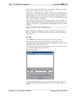
Page 38: ...twork without manually assigning each one a unique IP address NOTE The TPMC 12 ships with DHCP enabled Static IP addresses on a dedicated AV control system allow the integrator to have a fixed controllable network This helps maintain communication stability between Ethernet devices IP Table Touch IP Table on the setup menu to open the IP Table Setup window Edit remove or enter a control system s I...

Page 39: ...e is required for Ethernet communication Sharing Touch Sharing to open the Configure Shared Folders window This window is used to set up shared folders Sharing enables remote computers to view and or modify files stored on the touch screen Configure Shared Folders Window Touch Add New Share to browse and add directories with permission to read only or read write Touch Close after adding all folder...

Page 40: ...o reactivate the touch screen Hard Button Backlight Details The Hard Button Backlight can be varied from 0 to 100 To increase the brightness touch Up To decrease the brightness touch Down Misc Controls Details The Misc Controls section of the setup menu contains the Diagnostics and Keyboard buttons Diagnostics Touch Diagnostic to display the firmware version number see Installed Packs and to reset...

Page 41: ...25 to 100 with a default value of 90 The Default button restores the original Screen Position and Translucence settings as well as enabling display of Network messages A Test Message button lets you see the changes to popup message position and translucence Touch Close to close the popup window NOTE The default value for Screen Position is Lower Left Show Keyboard Touch the Keyboard button to disp...

Page 42: ...et in the VT Pro e or SIMPL Windows program The size will revert to the largest as determined by the firmware installed in the touch screen Exit the on screen keyboard by selecting by touching the X close button in the upper right corner of the keyboard window If the Keyboard button on the start menu is still visible you can also touch it to exit the keyboard Screen Brightness Details The Screen B...

Page 43: ...ssary connections as called out in the illustration that follows this paragraph Refer to Network Wiring CAT5 Wiring and QuickMedia Wiring on page 13 before applying power If the TPMC CH IMC is to be used for connecting CAT5 audio and CAT5 video refer to the latest revision of the TPMC CH IMC Operations Guide Doc 6345 for more information Hardware Connections for the TPMC 12 NET To Control System a...

Page 44: ...NOTE For optimum performance Crestron strongly recommends using CresCAT QM cable available from Crestron Other high quality low skew CAT5e CAT6 wiring may also be used with varying performance NOTE For CAT5 and QuickMedia connections use Crestron Certified Wire NOTE A QuickMedia transmitter such as the QM TX is required in order to connect conventional video and audio sources to the QM IN port The...

Page 45: ...count for limits based upon the touch screen power requirements Refer to the latest version of the TPMC CH IMC Interface Module Operations Guide Doc 6345 and Network Wiring on page 13 QM TX QuickMedia Transmitter The QM TX QuickMedia Transmitter sold separately can be used to connect a video or audio source to a QuickMedia network without a locally available QM transmitter such as the QM WMC The Q...

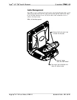
Page 46: ...ors on cables and the touch screen Refer to the following illustration to use the built in strain relief mechanism to secure cables to the touch screen TPMC 12 Cable Management Remove the four cover screws to access the I O panel Route I O cables under the metal bracket Use screws and metal bracket to clamp I O cables in place 42 Isys 12 Tilt Touch Screen TPMC 12 Operations Guide DOC 6675C ...

Page 47: ...ace of the touch screen free of dirt dust or other materials that could degrade optical properties Long term contact with abrasive materials can scratch the surface which may detrimentally affect image quality For best cleaning results use a clean damp non abrasive cloth with any commercially available non ammonia glass cleaner Bezels may not provide a complete watertight seal Therefore apply clea...

Page 48: ...Programming with Crestron SystemBuilder SystemBuilder is a comprehensive programming environment Appropriate for most systems it can quickly and easily generate a complete working program including both control processor logic and touch screen graphics Programming with SIMPL Windows NOTE While SIMPL Windows can be used to program the TPMC 12 it is recommended to use SystemBuilder for configuring a...

Page 49: ... the control system displays the device in the appropriate slot s with a default Net ID or IP ID as shown in the following illustration NOTE In the following illustration there is both an Ethernet device in Slot 8 and a Cresnet device in Slot 9 It is possible to have both types of device attached to a control system as long as the control system has either a built in or expansion Ethernet interfac...

Page 50: ...for each device Each TPMC 12 device is assigned a different Net ID or IP ID number as it is added 3 If necessary double click a device to open the Device Settings window and change the Net ID or IP ID as shown in the following figures Device Settings Crestron TPMC 12 Cresnet Window 46 Isys 12 Tilt Touch Screen TPMC 12 Operations Guide DOC 6675C ...

Page 51: ...bjects Multi mode objects offer high performance programming The single most advanced VT Pro e high performance programming technique involving the TPMC 12 is the concept of multi mode objects A multi mode object i e button legend etc is an object drawn on a VT Pro e page that can have one or more active and inactive visible settings modes For examples refer to www crestron com exampleprograms and...

Page 52: ...em the associated 8 bits of video memory for every screen pixel contain a value referring to a location in an 8 bit color table In this way any one of the specific 256 color table locations is assigned to a pixel A 16 bit highcolor system is considered sufficient to provide life like colors It is encoded using 5 bits to represent red 5 bits to represent blue and since the human eye is more sensiti...

Page 53: ... size using the Image Properties window A reduction in image size will save a considerable amount of memory space for your project In VT Pro e the Compress checkbox permits the image to be compressed when compiling The 16 Bits checkbox converts a 24 bit or 32 bit image to 16 bits This conversion to a 16 bit image may cause the loss of some subtle shading To compensate for this use the dithering to...

Page 54: ...ultibyte character fonts require more than the usual eight bits to specify a character This occurs when a language has more than 256 characters 28 in a font For example Chinese fonts contain several thousand characters Other multibyte languages include Japanese and Korean There are two separate applications with multibyte characters static text on buttons and indirect text on buttons No touch scre...

Page 55: ...plications are embedded in a VT Pro e TPMC 12 project Refer to illustration on the following page Adobe Reader Microsoft Excel Viewer Microsoft Internet Explorer Microsoft Word Viewer MJPEG Viewer NetMeeting PowerPoint Viewer Real Player Remote Desktop VNC Viewer Windows Media Player WordPad The embedded applications have the following features All embedded applications listed in the VT Pro e Proj...

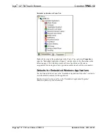
Page 56: ...w permits a choice of positions on the screen assignment of an analog touch join type and number and a show hide join number Defaults for Embedded Windows Applications Use the Default Path text box in the Embedded Applications Properties window to enter the default document for the application Edit the Default Position and Size in the Embedded Application Properties window to point to your new loc...

Page 57: ...mple has Join 10 assigned to a button that is used to toggle the state of Internet Explorer Press10 is routed to the clock line of a Toggle symbol The output of the toggle is routed to fb11 Join 11 is referred to as the Open Close State Digital Join The feedback signal of the Open Close State Digital Join is used to Open Close the application In this example when fb11 goes high Internet Explorer o...

Page 58: ...se_IE_FB is high If the user presses the X on IE IE closes The next time they touch button 10 Open Close_IE_FB will go low which tries to close the application However the application is already closed We need to reset the state of the toggle to keep in sync with the actual state of the application The Press signal of the Open Close State Digital Join can be used to know the true state of the appl...

Page 59: ... help file for details There is a single method of communication TCP IP communication Ethernet Communication PC Running Crestron Toolbox LAN TPMC 12 The TPMC 12 connects to PC via Ethernet 1 Enter the IP address IP mask and default router of the TPMC 12 via the Crestron Toolbox Functions Ethernet Addressing otherwise leave DHCP enabled The unit ships with DHCP enabled 2 Confirm Ethernet connection...

Page 60: ... programs projects or firmware Program Checks Actions that can be performed on the TPMC 12 vary depending on whether it is connected via Cresnet or Ethernet Cresnet Connections For Cresnet connections using Crestron Toolbox display the network device tree Tools Network Device Tree View to show all network devices connected to the control system Right click on the TPMC 12 to display actions that ca...

Page 61: ...rastructure Since the TPMC 12 does not use a traditional hard drive but rather an image that is restored every time the touch screen is rebooted any virus infection is cleared immediately after a reboot However using the currently available tools and techniques Crestron has provided an infrastructure that protects against possible virus infections 1 Executables Scripts brought in on external media...

Page 62: ...disabled and has no Java Virtual Machine installed These applets cannot run on the TPMC 12 NOTE While browsing the Internet with the TPMC 12 clicking on a link may cause a message box titled Restrictions to appear that contains the text This operation has been cancelled due to restrictions in effect on this computer Please contact your system administrator If this message appears checking Enable P...

Page 63: ...ect wiring to all connectors Touch screen Cresnet ID is not set to match the Net ID in the SIMPL program Use Crestron Toolbox to poll the network Verify that the Cresnet ID for the touch screen is properly set to match the Net ID in the SIMPL program Touch screen is not responding Touch screen Cresnet ID is not unique two or more units share the same ID Use Crestron Toolbox to poll the network and...

Page 64: ...ormance over the full range of your installation topology use Crestron Certified Wire only Failure to do so may incur additional charges if support is required to identify performance deficiencies because of using improper wire Calculate Power CAUTION Use only Crestron power supplies for Crestron equipment Failure to do so could cause equipment damage or void the Crestron warranty CAUTION Provide ...

Page 65: ...he Cresnet connector and tighten the retaining screw Repeat the procedure for the other three conductors Add Hubs Use of a Cresnet Hub Repeater CNXHUB is advised whenever the number of Cresnet devices on a network exceeds 20 or when the combined total length of Cresnet cable exceeds 3000 feet 914 meters Reference Documents The latest version of all documents mentioned within the guide can be obtai...

Page 66: ...e available as manual updates These updates are solely electronic and serve as intermediary supplements prior to the release of a complete technical documentation revision Check the Crestron Web site periodically for manual update availability and its relevance Updates are identified as an Addendum in the Download column 62 Isys 12 Tilt Touch Screen TPMC 12 Operations Guide DOC 6675C ...

Page 67: ...ts purchased directly from Crestron or an authorized Crestron dealer Purchasers should inquire of the dealer regarding the nature and extent of the dealer s warranty if any Crestron shall not be liable to honor the terms of this warranty if the product has been used in any application other than that for which it was intended or if it has been subjected to misuse accidental damage modification or ...

Page 68: ... an upgrade any transfer must also include all prior versions of the SOFTWARE o EXPORT RESTRICTIONS You acknowledge that SOFTWARE is subject to U S export jurisdiction You agree to comply with all applicable international and national laws that apply to the SOFTWARE including the U S Export Administration Regulations as well as end user end use and destination restrictions issued by U S and other ...

Page 69: ...that personally identifies you Internet Gaming Update Features If the SOFTWARE provides and you choose to utilize the Internet gaming or update features within the SOFTWARE it is necessary to use certain computer system hardware and software information to implement the features By using these features you explicitly authorize MS Microsoft Corporation and or their designated agent to use this info...

Page 70: ...Crestron Electronics Inc Operations Guide DOC 6675C 15 Volvo Drive Rockleigh NJ 07647 2020617 Tel 888 CRESTRON 12 11 Fax 201 767 7576 Specifications subject to www crestron com change without notice ...

Reviews: