


Camera Interface, Digital Servo Pan Tilt Head
Crestron
C2N-CAMIDSPT
16
•
Camera Interface, Digital Servo Pan Tilt Head: C2N-CAMIDSPT
Operations Guide - DOC. 6262A
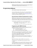
assembly most closely balances (refer to the following illustration). At
this location, reassemble and tighten the mounting screws and washers.
7. Measure the distance from the bottom of the support bracket to the
optical centerline of the camera/lens assembly. In the illustration, the
height of the optical centerline would be for a box camera style only.
The vertical centerline for an ENG camera will be different.
Positioning the Camera/Lens Assembly on the Mounting Plate/Support Bracket Assembly
ROUND
OBJECT
MOUNTING
PLATE
LENS
CAMERA
1.5 in
(3.81 cm)
Tilt Axis
Centerline
Mark
CAMERA/LENS
SUPPORT BRACKET
8-32 x 1/2 inch
Socket Button Head
Screws w/Washers
Socket Head Cap
Screw w/Flat Washer
Height of
Optical
Centerline
Balance
Centerline
Mark
Centerline
Intersection
MOUNTING
PLATE
8. Disassemble the camera/lens assembly from the support bracket, and
mark the intersection point of the optical centerline distance and the
balance centerline on the mounting plate.
9. Position the mounting plate/support bracket assembly on the tilt hub so
the centerline intersection (Step 8) is aligned with the marked
centerline of the tilt hub axis, which can be seen through the screw
slots of the mounting plate. Use four 6-32 x ½-inch socket button-head
screws and washers (supplied) to secure the mounting plate to the
CAMIDSPT tilt disc. Install the screws into the holes that are as far
apart as possible.
10. Reattach the camera/lens assembly to the support bracket, allowing
minimum clearance between the camera/lens assembly and the
mounting plate.
11. Mount the CAMIDSPT with attached camera/lens assembly to the
desired location. The unit mounts on its pan hub base with four ¼-20
socket-head screws. The length of the screws should extend 1/2-inch to
5/8-inch maximum through the mounting flange. Longer screws will


