background image

22 • ZUM-HUB4

Product Manual — Doc. 9094B

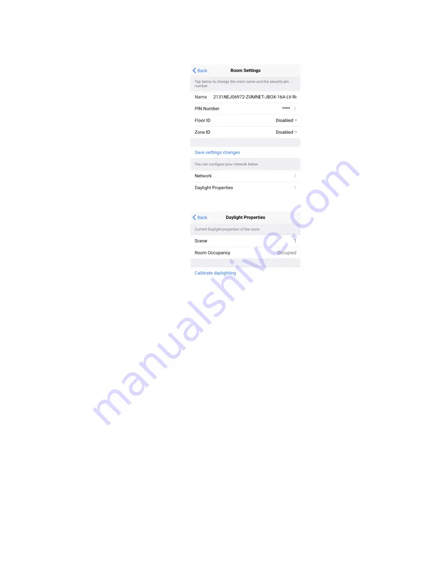
c. Click Daylight Properties.

d. Click Calibrate Daylighting.

To indicate that Daylighting has been calibrated, the lights in the space will turn full
on, turn off, and then back on with the Daylighting settings. Whenever Scene 1 is
recalled, the Daylighting settings are initiated.

Log into the Web-Interface

The ZUM-HUB4 is configured using the web interface. Connect to the device by entering the
device hostname into a web browser. The hostname is comprised of "ZUM-HUB4-" followed by
the entire MAC address (e.g., ZUM-HUB4-00107FCA1112). The New User Registration screen is
displayed during the first connection. Enter the user's Username, Password, Firstname,
Lastname, and Email Address, and then click Submit.

Summary of Contents for 4 Series

Page 1: ...ZUM HUB4 4 Series Control Processor for Zūm Lighting Control System Product Manual Crestron Electronics Inc ...

Page 2: ...rce Crestron the Crestron logo 4 Series Cresnet XiO Cloud Crestron Toolbox SIMPL and Zūm are either trademarks or registered trademarks of Crestron Electronics Inc in the United States and or other countries BACnet is either a trademark or registered trademark of American Society of Heating Refrigerating and Air Conditioning Engineers Inc in the United States and or other countries Bluetooth is ei...

Page 3: ...ions 10 Configuration 13 Zūm App Configuration 13 Zūm App Main Screen 13 Calibrate Daylighting Settings 18 Log into the Web Interface 22 Web Interface Overview 23 Category View System View and Settings View 24 Global Settings and Actions for the ZUM HUB4 25 Navigation Toggle 26 Device Information and Status 26 Web Interface Configuration 26 Discover Rooms 27 Add a Room Category 28 Rename a Room Ca...

Page 4: ...Manage Settings 54 Manage Users 58 Manage External Controls 60 Manage Commissioning 63 Review Device Information and Status 66 Reboot ZUM HUB4 67 ii Contents Product Manual Doc 9094B ...

Page 5: ...iii Contents Product Manual Doc 9094B ...

Page 6: ...r Supply Contains o ZUM HUB4 and PW 2420RU power pack o ZUMNET GATEWAY Zūm Net Wireless Gateway for Zūm Light Control System o PW 2407WU Wall Mount Power Pack 24VDC 0 75A 2 1 mm Universal For use with the ZUMNET GATEWAY l ZUML HUB4 PAK Zūm Lighting Control Processor Panel Basic Contains o ZUM HUB4 and PW 2420RU power pack o CEN SW POE 5 5 Port PoE Switch o GLEX FT 24 HC Feed Through Enclosure 24 C...

Page 7: ...l Universal 100 240V external power supply Zūm Net Wired Technology Zūm Net wired technology offers room to room communication Control a room with one Zūm Net device ZUMNET JBOX DALI ZUMNET JBOX 16A LV sold separately and daisy chain up to 20 Zūm Net devices with CBL CAT5E ZUMNET P cable For centralized management of a Zūm Wired System connect the chain directly to a ZUM HUB4 or multiple chains to...

Page 8: ...ramming Zūm Wireless Integration Integration with existing Zūm Wireless installations is achieved with a ZUMNET GATEWAY not supplied which connects to the ZUM HUB4 via Ethernet Zūm System Integration with Other Crestron Control Systems In addition to managing rooms equipped with Zūm lighting control the ZUM HUB4 enables integration with other Crestron systems over an Ethernet connection Two method...

Page 9: ... Connects to the customer s LAN CONTROL SUBNET 1 8 pin RJ 45 connector female 10Base T 100Base TX 1000Base T Ethernet port Provides a dedicated local network for Zūm Net wireless gateways NET 1 4 pin 3 5 mm detachable terminal block Not used 24VDC 2 0A 1 2 1 x 5 5 mm DC power connector 24VDC power input PW 2420RU power pack included Passes through to NET port G 1 6 32 screw Chassis ground lug COMP...

Page 10: ...ted an error message HW R 1 Recessed pushbutton for hardware reset SW R 1 Recessed pushbutton for software reset LAN rear 2 Bi color green amber LEDs Left LED indicates Ethernet link status and connection speed Right LED indicates Ethernet activity CONTROL SUBNET rear 2 Bi color green amber LEDs Left LED indicates Ethernet link status and connection speed Right LED indicates Ethernet activity ...

Page 11: ...CP SSL TLS SSH SFTP SSH File Transfer Protocol FIPS 140 2 compliant encryption IEEE 802 1X SNMP IPv4 or IPv6 Active Directory authentication IIS v 6 0 web server Control Subnet 10 100 1000 Mbps Ethernet auto switching auto negotiating auto discovery full half duplex DHCP server DNS Server port forwarding isolation mode USB Supports computer console via front panel USB 2 0 device port Connectors an...

Page 12: ...e ZUM HUB4 has generated an error message HW R 1 Recessed pushbutton for hardware reset SW R 1 Recessed pushbutton for software reset LAN rear 2 Bi color green amber LEDs Left LED indicates Ethernet link status and connection speed Right LED indicates Ethernet activity CONTROL SUBNET rear 2 Bi color green amber LEDs Left LED indicates Ethernet link status and connection speed Right LED indicates E...

Page 13: ...thin the control system program and provide virtual connections for all the necessary intersystem control signals A separate dedicated module is required for each external and mirrored room Control systems are limited in the number of modules supported ranging from 0 to 1000 depending on the model For further assistance please contact Crestron Commercial Lighting Support via email at clclighting c...

Page 14: ...Product Manual Doc 9094B ZUM HUB4 9 Dimension Drawings ...

Page 15: ...he screws removed in the previous step to attach the included rack ears to the device 3 Mount the device into the rack using four mounting screws not included Place onto a Flat Surface When placing the device onto a flat surface or stacking it with other equipment attach the included rubber feet near the corners on the underside of the device Make Connections The ZUM HUB4 has a dedicated Control S...

Page 16: ... have been made NOTES l Ensure the unit is properly grounded by connecting the chassis ground lug to an earth ground building steel l The ZUM HUB4 can be powered with the included 24VDC power pack l Do not connect the CONTROL SUBNET port to the LAN The CONTROL SUBNET port must be connected only to Crestron Ethernet devices For details on using the Control Subnet refer to the 4 Series Control Syste...

Page 17: ... l Daisy chain up to 20 Zūm Net devices up to a maximum of 328 ft 100 m per leg with purple CBL CAT5E ZUMNET P RJ 45 cables sold separately l System sensors communicate digitally via Zūm Link Non system sensors communicate via an analog connection on a Zūm Wired J BOX ...

Page 18: ... connection is required to configure a Zūm wired space with the Zūm app This section provides the following information Zūm App Configuration Log into the Web Interface Web Interface Overview Web Interface Configuration Zūm App Configuration Download the Zūm app from the Google Play online store To use the Zūm app 1 Enable Bluetooth wireless connection on your device to communicate with the Zūm sp...

Page 19: ...14 ZUM HUB4 Product Manual Doc 9094B ...

Page 20: ...PLUG load controller n Override The state of the load when Override is recalled Click the toggle to turn the load on or off during Override n Assign the occupancy mode Occupancy menu vacancy mode Vacancy menu vicinity mode Vicinity menu and daylight harvesting Photo menu to specific load controllers o ZUMLINK JBOX 20A SW load controller n Closed Click the toggle to turn the load on or off n Overri...

Page 21: ...t for the specified scene n Export to Hub Name and send information to ZUM HUB4 for macro actions l Load Shedding Set the maximum levels for load shedding l Load Sensor Groups Create groups within the room l Current Scene Displays the current room scene l Occupancy Status Displays occupied or vacant If any area of the room is occupied then the status is Occupied When all areas of the room are vaca...

Page 22: ... to left until the blue Edit button appears Use the edit screen to change the name of the device and the name of the device functions Also identify or edit the connected devices 4 Current Template Settings Choose Open room template Save room template or Share room template ...

Page 23: ...yed using the Send configuration to room button 6 Revert changes Restore all non deployed changes made since launching the app Calibrate Daylighting Settings The photocell component of a load controller detects the amount of ambient light in the room When a space is calibrated for Daylighting and Scene 1 is called the photocell will detect the ambient light levels and dim the lights accordingly Ca...

Page 24: ...t settings 1 Assign the photocell component to the load controller that will participate in Daylighting a From the Main screen click Configuration b Click Load Controllers c Click the desired load controller d For Photo select a photocell from the drop down menu ...

Page 25: ...e room a Navigate back to the Main screen b Click Send configuration to room A confirmation window opens stating that the app will disconnect from the room Click OK to continue or Cancel to close without sending the configuration The Retrieving Data Map screen displays ...

Page 26: ...ick Configuration b Click Scenes c Select Scene 1 Daylighting is only available for Scene 1 d Adjust the loads in the space to the appropriate level based on the amount of natural light NOTE DO NOT click Save current levels 4 Calibrate Daylighting a Navigate back to the Main screen b Click Room Settings ...

Page 27: ...ecalled the Daylighting settings are initiated Log into the Web Interface The ZUM HUB4 is configured using the web interface Connect to the device by entering the device hostname into a web browser The hostname is comprised of ZUM HUB4 followed by the entire MAC address e g ZUM HUB4 00107FCA1112 The New User Registration screen is displayed during the first connection Enter the user s Username Pas...

Page 28: ...Product Manual Doc 9094B ZUM HUB4 23 Web Interface Overview The web interface gives users the ability to configure room behavior globally across the ZUM HUB4 by Room Category by Floor and by Room ...

Page 29: ...vered by the ZUM HUB4 Room Categories are intended to be groupings of all rooms that are a similar type for example office or conference rooms to provide easy monitoring and control Rooms that have not been assigned to a Room Category are kept in the Unassociated category Select the Schedule tab to edit default behavior for Day Patterns Room States and Holidays l Manage Rooms on page 37 l Manage R...

Page 30: ...and Commissioning The Settings tab is open by default l Manage Settings on page 54 l Manage Users on page 58 l Manage External Controls on page 60 l Manage Commissioning on page 63 Global Settings and Actions for the ZUM HUB4 Apply settings that effect all devices discovered by the ZUM HUB4 regardless of the room room category or floor the device is assigned ZUM HUB4 actions l Configure Demand Res...

Page 31: ...rface Refer to Review Device Information and Status on page 66 Web Interface Configuration After using the Zūm app to setup Zūm spaces and logging into web interface configure the ZUM HUB4 Discover Rooms Add a Room Category Rename a Room Category Turn Rooms On or Off Set the Bluetooth PIN Configure the Demand Response Mode and Level Manage Rooms Schedule Room Behavior Manage Floors Manage Devices ...

Page 32: ...age 13 l Log into the Web Interface on page 22 Discover Rooms To discover rooms 1 Click the Actions menu 2 Click Discover The Discover window opens 3 Select the type of rooms you want to discover 4 Click Discover to Discover rooms or close the window During the discover process a Stop button displays as an option to stop discovering ...

Page 33: ...s Rename a Room Category Room Category names can be renamed to provide a clear description of the connected rooms To rename the Room Category name 1 Click the menu beside the Room Category name 2 Click Rename 3 Click to save the Room Category or to cancel For more information about Room Categories refer to Manage Room Categories Turn Rooms On or Off Control a room by turning on off the all rooms a...

Page 34: ...On Off All Discovered Devices To turn all devices on off 1 Open the Category View 2 Click the menu beside the ZUM HUB4 3 Click All Off or All On Turn On Off a Room Category To turn all devices on off in a Room Category 1 Open the Category View 2 Click the menu beside the Room Category name 3 Click All Off or All On Turn On Off a Floor To turn all devices on off on a Floor 1 Open the System View 2 ...

Page 35: ...IN is set for a device it remains until manually changed For example if a device moves to a different room or floor the Bluetooth PIN does not automatically inherit the PIN set for the new location The device keeps the PIN previously set This section provides the following information l Set the Bluetooth PIN for All Discovered Devices below l Set the Bluetooth PIN for a Room Category on the facing...

Page 36: ...o set the Bluetooth PIN for devices in a Room Category 1 Open the Category View 2 Click the menu beside the Room Category name 3 Click Bluetooth PIN 4 Set the PIN 0 to 9999 5 Click to save or to cancel Set the Bluetooth PIN for a Room To set the Bluetooth PIN for devices in a Room ...

Page 37: ...N set the PIN 0 to 9999 4 Click Send to send changes to the room or close the Control Room window to discard unsaved changes Set the Bluetooth PIN for a Floor To set the Bluetooth PIN for devices on a floor 1 Open the System View 2 Click the menu beside the Floor name 3 Click Bluetooth PIN 4 Set the PIN 0 to 9999 5 Click to save or to cancel ...

Page 38: ...ice it remains until manually changed For example if a device moves to a different room or floor the Demand Respond Level does not automatically inherit the level set for the new location The device keeps the level previously set This section provides the following information l Configure Demand Response Mode below l Set the Demand Response Level for All Discovered Devices on the next page l Set t...

Page 39: ...g Set the Demand Response Level for All Discovered Devices To set the Demand Response Level for all devices 1 Open the Category View 2 Click the menu beside the ZUM HUB4 3 Click Demand Response Level 4 Set the light level 0 to 100 5 Click to save or to cancel Set the Demand Response Level for a Room Category To set the Demand Response Level for devices in a Room Category 1 Open the Category View 2...

Page 40: ... Response Level for a Room To set the Demand Response Level for devices in a Room 1 Open the Category View and the Room tab 2 Click the to open the Control Room window 3 For Demand Response set the level 0 to 100 4 Click Send to send changes to the room or close the Control Room window to discard unsaved changes ...

Page 41: ...he Demand Response Level for a Floor To set the Demand Response Level for devices on a Floor 1 Open the System View 2 Click the menu beside the Floor name 3 Click Demand Response Level 4 Set the light level 0 to 100 5 Click to save or to cancel ...

Page 42: ...m View tabs Rooms must be discovered by the ZUM HUB4 before performing any procedure in this section Refer to Discover Rooms on page 27 Review Rooms The Room list displays room information including built in components l Room Displays the room name l Category Displays the Room Category l Floor ID Displays the Floor ID The Floor ID can be set in the Hardware Management tab of the Systems View A Flo...

Page 43: ...n External room o Mirror Module Indicates whether the room is associated with a Mirror Room o Occupancy Sensor State Displays if the Occupancy Sensor is Enabled or Disabled o Plug Load State Displays if the Plug Load is ON or OFF o Last Scene Changed Displays the date and time of the last Scene change o Last Online Status Changed Displays the date and time of the last Online Status change o Last O...

Page 44: ...gory Floor ID Host Name Status Occ Active Scene or Next Event 3 Click the desired room name Add a Room to a Room Category To move a room to a different Room Category 1 Click on the ZUM HUB4 or on a Room Category 2 Select the desired room or rooms 3 Click the Associate Rooms menu 4 Select the desired Room Category 5 A confirmation dialog opens Click Yes to add the room s the Room Category or No to ...

Page 45: ...m 1 Click on the ZUM HUB4 or on a Room Category 2 For the desired room click the to open the Control Room options Lighting Scene To select the Lighting Scene set in the Room 1 Select a Lighting Scene from the drop down menu 2 Click Send to send changes to the room or close the Control Room to discard unsaved changes Plug Loads This setting is only active for rooms with a Plug Load Controller 1 Sel...

Page 46: ...l for devices in a room 1 Set the level 0 to 100 2 Click Send to send changes to the room or close the Control Room to discard unsaved changes Refer to Configure the Demand Response Mode and Level on page 33 for more information Schedule Room Behavior The Schedule tab displays and allows you to edit the device calendar Day Patterns Room States Holidays and the astronomical clock The calendar displ...

Page 47: ...date A menu displays a list of the available Day Patterns 4 Select the desired Day Pattern Day Patterns A Day Pattern consists of various Room States that are assigned throughout the day Each category can be assigned a different schedule of room states in a given day pattern To access the Day Patterns menu click the Schedule tab and click to expand the scheduling menus ...

Page 48: ...dow opens 2 Click Yes to delete the Day Pattern or click No to keep the Day Pattern NOTE A Default Day Pattern such as Holidays Weekend and Workdays cannot be deleted Configure Day Patterns After adding a Day Pattern the Add Day Pattern window opens Alternatively clicking beside a Day Pattern opens the Edit Day Pattern window These windows display two menus Room State Schedule and Sunrise Sunset S...

Page 49: ...w opens 2 Select the desired Room State from the Name drop down menu The default Room State selections are examples of possible Room State applications and can be edited as needed l Automatic Mode l Default Use Occupancy l Energy Saving l Manual Control l Morning Turn Off l Morning Turn On l Sweep Off 3 Select the desired Room State start time from the Time drop down menu 12 AM 11 45 PM 4 Click Ok...

Page 50: ... Schedule assigns a Room State to a Room Category based on the Day Pattern and the sunrise or sunset Only one Sunrise event and one Sunset event can be set for a Room Category per day To assign Room States based on the sunrise or sunset 1 Expand the Sunrise Sunset Schedule menu 2 Locate the Room Category 3 Adjust the settings in the Sunrise events column and or the Sunset events column l ENABLE Cl...

Page 51: ... of events as well as a set of behaviors for a Room Category It identifies the lighting scene that is recalled the functionality of the occupancy sensor and the plug load controllers To access the Room States menu click the Schedule tab and click to expand the scheduling menus ...

Page 52: ...abled to allow occupancy sensing Disabled to turn occupancy sensing off or Unaffected to use the setting of the previous event l Plug Loads Select On to turn on the Plug loads Off to turn off the Plug Loads or Unaffected to use the setting of the previous event 3 Click Cancel to close the window without saving or Add to add the Room State Delete a Room State To delete a Room State 1 Click to delet...

Page 53: ...Schedule tab To access the Holidays menu click the Schedule tab and click to expand the scheduling menus Add Holidays Click Add Holiday and type the desired Holiday name Click to save the name click to cancel Delete a Holiday To delete a Holiday 1 Click to delete a Holiday A confirmation window opens 2 Click Yes to delete the Holiday or click No to keep the Holiday NOTE A default Holiday cannot be...

Page 54: ...on Turn the toggle off to prevent the holiday from appearing in the calendar on the Schedule tab When the toggle is off the default Day Pattern is applied instead l Observed Select a date to observe the holiday 3 Click Add to add the Holiday or Cancel to close the window Manage Floors Rooms must be discovered by the ZUM HUB4 before performing any procedure in this section Refer to Discover Rooms o...

Page 55: ...d expand the Wireless menu View information about the gateway assign Floor or Zone IDs and identify or remove a gateway To view move and delete the rooms assigned to the gateway refer to Review Rooms Assigned to a Gateway on the facing page Information about the gateway l Gateway Hostname Displays the gateway s name l IP ID Displays the gateway s IP ID l Serial Number Displays the gateway s serial...

Page 56: ...way a Zone ID Assigning a Zone ID to a gateway helps gateways discover wireless devices with the matching Zone ID Set a device s Zone ID in the Zūm app before discovering the devices on the ZUM HUB4 The Zone ID drop down menu options are letter groupings AA to AZ and BA to BF Identify a Gateway To identify a gateway click The SETUP LED on the gateway flashes Remove a Gateway To delete a gateway cl...

Page 57: ...thout deleting the room Wired Devices Access wired Room Access Points in the Hardware Management tab and expand the Wired menu A Room Access Point RAP is the main device in the room View information about the RAP assign Floor or Zone IDs or remove an RAP To view devices connected to RAP refer to Review RAP Components on the facing page l Room Access Point Hostname Displays the main device s name l...

Page 58: ... load controller a Zone ID The Zone ID drop down menu options are letter groupings AA to AZ and BA to BF Remove a RAP To delete a load controller click A confirmation window opens Click Yes to delete the load controller or No to keep the load controller Review RAP Components Click next to a load controller to view connected devices l Device Displays child devices connected to the parent load contr...

Page 59: ...onnected loads n 2 Occupancy sensor component Uses occupancy to control the connected loads n 3 Photocell component Uses ambient light to control the connected loads n Change the component name by using the Zūm App o Model Displays the device model o Serial Number Displays the component s serial number o Firmware Version Displays the component s firmware version o Status Displays Online or Offline...

Page 60: ...Cloud or Removeable Media 5 If using removeable media insert the device 6 Check the box under Action for the devices whose firmware you want to update 7 Click Update Now General Displays the date time and time zone To change the date and time 1 Open Settings View 2 Click Settings 3 Click General 4 Enter new values in the fields 5 Click to save the changes or to discard changes NOTE Changing these ...

Page 61: ...rd changes NOTE Changing these settings requires an immediate system reboot A confirmation windows opens Click Yes to reboot or No to close the window Network Displays the Ethernet settings To change the Ethernet settings 1 Open Settings View 2 Click Settings 3 Click Network 4 Enter new values in the fields Some fields are not available if DHCP is on 5 Click to save the changes or to discard chang...

Page 62: ...onfirmation windows opens Click Yes to reboot or No to close the window Services Displays Cloud Settings To turn Cloud Configuration Service on or off 1 Open Settings View 2 Click Settings 3 Click Services Cloud Configuration Service is on by default 4 To turn off Cloud Configuration Service click the toggle 5 Click to save the changes or to discard changes NOTE Changing these settings requires an...

Page 63: ...are permitted to use uppercase letters A Z lowercase letters a z digits 0 9 and special characters _ The password must be 8 to 12 characters is required to contain at least one uppercase letters A Z lowercase letters a z digits 0 9 and special characters Create a New User To create a new User 1 Open Settings View 2 Click Users 3 Click 4 Enter the user details 5 Click Save to save the new user or C...

Page 64: ...IMPL software module NOTES l SIMPL software modules are provided for use in commissioning a Crestron control system to work with the ZUM HUB4 The software modules run within the control system program and provide virtual connections for all the necessary intersystem control signals A separate dedicated module is required for each external and mirrored room Control systems are limited in the number...

Page 65: ...ns for all the necessary intersystem control signals A separate dedicated module is required for each external and mirrored room Control systems are limited in the number of modules supported ranging from 0 to 1000 depending on the model For further assistance please contact Crestron Commercial Lighting Support via email at clclighting crestron com or by calling 855 644 7643 External Module Connec...

Page 66: ...ings View 2 Click the External Controls tab and expand the External Controls menu 3 Click 4 Enter new values in the fields 5 Click to save or to cancel Delete Existing Macro To delete an existing macro 1 Open Settings View 2 Click the External Controls tab and expand the External Controls menu 3 Click A confirmation window opens 4 Click Yes to delete the macro or No to cancel BACnet Configuration ...

Page 67: ... Rooms The number of rooms with BACnet l Property List Allows users to select which objects are enabled for all rooms l Room Name The name of the room l Base ID Orders the device in the system and assigns the object IDs l ID Range The range of Object IDs that the room can use l Object List Displays a list of all Object IDs Object Names and Object Types within the selected room A blue checkmark ind...

Page 68: ...earch extract edit or delete an existing template Add a New Template To add a new room template 1 Open Settings View 2 Click the Commissioning tab and expand the Template Management menu 3 Click Upload The Upload window opens 4 Click Choose to browse for a new template 5 Select the template 6 Click Upload to add the template to the Template Management menu Cancel to choose a different template or ...

Page 69: ...and the Template Management menu 3 If necessary use the Search bar to find a room template 4 Click A confirmation window opens 5 Click Yes to delete the template or Cancel to close the window Extract Template To extract a room template from another room 1 Open Settings View 2 Click the Commissioning tab and expand the Template Management menu 3 If necessary use the Search bar to find a room templa...

Page 70: ... edit a template assignment 1 Open Settings View 2 Click the Commissioning tab and expand the Mapping and Template Deployment menu 3 Click beside the desired room If necessary use the Search bar to find the room A window opens 4 From the Select Template drop down menu choose the desired template The remaining data specifies the room information the devices and components affected and the selected ...

Page 71: ...on and Status View the Demand Response status system alerts help information or sign out of the web interface Demand Response Status Demand Response is enabled Demand Response is disabled System Information Displays system alerts Help Click to view the help file ...

Page 72: ...ck to bring up the Sign Out pop up Click Sign Out to log out of the ZUM HUB4 Reboot ZUM HUB4 To reboot the ZUM HUB4 1 Click the Actions menu 2 Click Reboot The Confirmation window opens 3 Click Yes to Reboot or No to close the window without rebooting ...

Page 73: ...This page is intentionally left blank Product Manual Doc 9094B ZUM HUB4 68 ...

Page 74: ...Crestron Electronics Inc 15 Volvo Drive Rockleigh NJ 07647 Tel 888 CRESTRON Fax 201 767 7656 www crestron com Product Manual Doc 9094B 2055411 11 18 21 Specifications subject to change without notice ...

Reviews: