107
6. While supporting the bracket with one hand, turn over the system board and
place it on the worktable.
7. Return the CPU. See
Replacing the Central Processing Unit (CPU)
8. Connect the CPU fan cable to the CPU Fan 6 connector. See Figure 17 on
9. Insert the system board into the chassis, and carefully slip it under the five RFI
clips.
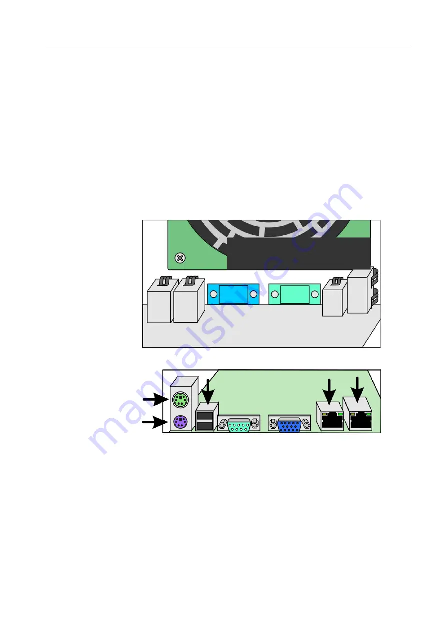
Figure 22: RFI-clip positions, internal view
Figure 23: RFI-clip positions, external view
10. Align the system board with the matching hole in each standoff insulator in the
chassis.
11. Insert the eight screws into the holes. Do not tighten the screws until all the
screws are inserted.
12. Return the rear fan. See
13. Return the memory modules. See
14. Return the FusionRA board. See
Note:
If you are reusing a metal bracket that was attached to a previous
system board, the glue may have weakened and lost some of its
adhesiveness. Therefore, make sure to support the bracket with one
hand when installing the system board to its upright position,
Attention:
Do not bend or damage the RFI clips.
Make sure that the five RFI
clips make firm contact with the external-port connectors. See Figure 23.
System Board
Summary of Contents for Color Controller C-80
Page 2: ......
Page 8: ...vi Color Controller C 80 1 0 Technical Manual...
Page 17: ...1 Product Overview Introduction 2 Product Configuration 4...
Page 22: ...6 Chapter 1 Product Overview...
Page 52: ...36 Chapter 2 First Time Setup and Configuration...
Page 103: ...87 5 Click Yes 6 Click OK 7 To enable the changes to take effect restart your computer...
Page 104: ...88 Chapter 4 Diagnostics and Troubleshooting...
Page 142: ...126 Chapter 5 Hardware and Maintenance Repairs...
Page 149: ......
Page 150: ......


