background image

12

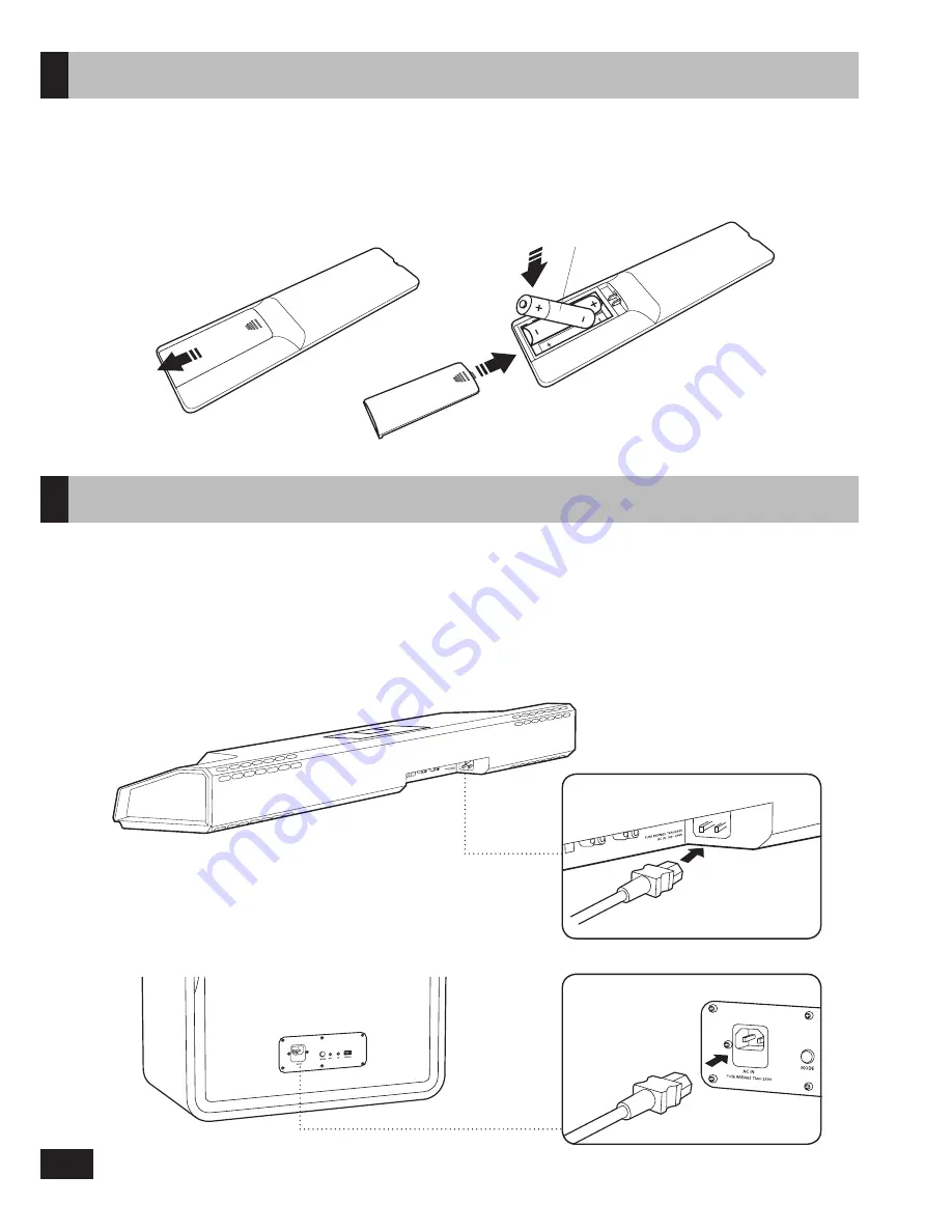
1.  Connect the power cords to the main unit and subwoofer. The sockets are located at the back of the units as    

  shown below. 

2.  Connect the power cords to the mains socket.
  For more information about the power supply and power consumption, refer to the respective product label. 

  (Main Unit : bottom panel, Subwoofer : rear panel)

Main Unit

Subwoofer

Connecting Electrical Power

1. Slide the battery cover in the direction of the arrow until it is completely removed.
2. Insert two AAA/LR03 batteries (1.5V) in the c/- polarity. 
3. Slide the battery cover back into position.

AAA/LR03 batteries 

(included)

(1)

(2)

(3)

Insert Remote Control Batteries 

Summary of Contents for Sonic Carrier MF8235

Page 1: ...Creative X Fi Sonic Carrier Model MF8235 Creative X Fi Sonic Carrier Subwoofer Model MF8240 USER MANUAL Firmware Version 1 6 onwards THE AUDIO OF TOMORROW ...

Page 2: ...7 Overview 8 Inserting Remote Control Batteries 12 Connecting Electrical Power 12 Setting Up the Subwoofer 13 Connecting Your Sonic Carrier 14 Wi Fi Setup 17 Mobile Apps 18 Performing Room Calibration 18 Specifications 20 Warranty 21 Appendix Wall Mounting the Main Unit 22 Contents ...

Page 3: ...ing material This will ensure the main unit and subwoofer are protected for future transport In the unlikely event you have a problem and must return it for service you must use the proper packing material Ship the equipment only in the original packing material otherwise the unit is not insurable by carriers You may cut the taped seams on the bottom flaps to flatten the cardboard cartons for easi...

Page 4: ...ard Tip box over gently onto side then flip box gently over again till top faces downward Place subwoofer upright and remove protective cover Open protective cover to find subwoofer feet Push out and remove transit protection foam blocks Subwoofer ...

Page 5: ... regulatory leaflets x8 IR remote control AAA battery x 2 for IR remote control Wall mount brackets x 2 thumbscrews x 2 Driver décor rings x 8 Power cable IR transmitter HDMI cable optional Subwoofer Power cable Link cable Safety and regulatory leaflets ...

Page 6: ...material such as wall board plaster hardwood or any rigid non sound absorbing material Avoid treating ceilings with acoustic damping materials For optimal playback the ceiling should be flat A shallow vaulted ceiling will provide an acceptable performance Chandeliers and can style lighting do not significantly interfere with or negatively impact the height effect Care for your Sonic Carrier Main U...

Page 7: ...s Firmware Updates The Sonic Carrier automatically checks for the latest firmware update each time it is powered on Follow the instructions on the main display to install the update We strongly advise you to update to the latest firmware Internet connection required Troubleshooting Guide Need help setting up your Sonic Carrier Access our troubleshooting guide at soniccarrier com support troublesho...

Page 8: ...witch between available outputs like Speaker Line Output or Bluetooth headphone Switch between mic adjustment modes Volume Key Reverb or Vocal Suppressor on off Press and hold to turn on off the microphone inputs Switch between available HDMI inputs LED 1 4 will be lit to indicate input source LED 1 4 will be dimmed to indicate TV ARC mode Press to cycle through available SD microSD cards Press an...

Page 9: ...r 5V 2A to power devices such as TV sticks No data transfer HDMI 2 0a input Overview CAUTION The front panel connectors are concealed by a magnetically latched flap that is hinged at the bottom Avoid applying excessive force to the flap Close the flap when access to the ports are not required or when the unit needs to be moved When tilting the main unit forward to facilitate cable connection remov...

Page 10: ...e keyboard mouse dongle Service Port No user accessible features Gigabit Ethernet to a wireless router modem for high speed Internet Optical inputs compatible with up to 24 bit 96kHz stereo PCM signals Power socket fuse ratings T4AH 250V AC IN 100 240V Connector Description Grounding post for optional ground connection in the event of noise interference on the Mic and Analog connections Grounding ...

Page 11: ...includingTV ARC Cycle through available SD microSD cards Press and hold to switch to SD direct music playback mode Switch to the last accessed USB input or cycle through available USB inputs Switch to the last accessed optical input or cycle through available optical inputs Output sound to main unit Mute line out and Bluetooth headphones out Output sound to line out Mute main unit and Bluetooth he...

Page 12: ...ly and power consumption refer to the respective product label Main Unit bottom panel Subwoofer rear panel Main Unit Subwoofer Connecting Electrical Power 1 Slide the battery cover in the direction of the arrow until it is completely removed 2 Insert two AAA LR03 batteries 1 5V in the correct polarity 3 Slide the battery cover back into position AAA LR03 batteries included 1 2 3 Insert Remote Cont...

Page 13: ... unit and subwoofer within 3m 10ft for the setup process 2 Connect the link cable bundled with the subwoofer to the main unit and the subwoofer If you wish to use a wired connection no further action is required 3 Ensure mains power is connected and switched on for both main unit and subwoofer 4 Power on the main unit The boot up process may take around a minute Link cable included 5 Press and hol...

Page 14: ...e audio settings to enable ARC Ensure the Sonic Carrier is powered ON and connected to the TV while the settings are being configured These are typically located under the Settings Audio Settings The settings should be selected as following TV audio output HDMI ARC Digital audio format PCM HDMI CEC for audio output Enable 5 After the setup is complete press the HDMI button on the main unit or remo...

Page 15: ...devices such as TV sticks maximum 5V 2A Connecting Your Sonic Carrier When a Dolby encoded input signal is detected it is automatically decoded and Dolby is displayed on the main display TOSLINK cable Press HDMI to cycle through the available HDMI inputs HDMI cable For the best possible audio quality please connect all HDMI source devices directly to the Sonic Carrier instead of the TV i e using H...

Page 16: ...ievable at your position in the listening environment Microphone feedback is produced when the signal from the microphone is amplified played back through the speakers and picked up again by the microphone To reduce acoustic feedback 1 Change the position and distance of the microphone relative to the Sonic Carrier The microphone should be pointed away from the Sonic Carrier at all times and keepi...

Page 17: ... is powered on and connected to your TV 2 Press HOME to display the Android video engine home screen 3 Select on the top right corner of the home screen using the cursor and OK buttons on the remote control 4 Select 5 Select the desired Wi Fi network to connect to enter the password and click Connect If the network connection is unsuccessful please ensure that WPA WPA2 encryption is used This coul...

Page 18: ... location The Wi Fi setup has been completed and the Sonic Carrier is connected to the same Wi Fi network as your mobile device Once the above has been checked do the following 1 Press HOME to view the Advanced Android Video Engine 2 If there is a red dot on the icon of the home page An updated Sonic Carrier Home firmware is available Select and the subsequent menu items demarcated with red dots t...

Page 19: ...t of surround sound you may want to increase the side left and side right levels Often small 0 5dB adjustments will yield significantly different results so increase or decrease the levels in small steps The following table gives a few examples of which parameters to adjust and how to adjust in order to obtain the sound you want Desired sound What to adjust Increase Decrease Clearer more prominent...

Page 20: ...ge Up to 10m 33ft measured in open space Specifications Keep this document for future reference Line level input Stereo 2Vrms analog RCA connectors Line level ouput Stereo 2Vrms analog RCA connectors Auxiliary input Stereo 1Vrms analog 3 5mm connector Microphone inputs 2 x microphone connector supporting most dynamic microphones USB host 2 x USB 2 0 type A connector for USB flash drives HDDs keybo...

Page 21: ...s or workmanship b Damagecausedbynormalwearandtear abnormaluseorconditions misuse neglect abuse accident improperhandlingorstorage defectsordamagesresulting from service testing adjustment installation maintenance alteration including without limitation software changes or modification in any way by someone other than Creative or its authorised service centres improper use of any electrical source...

Page 22: ... Hand drill Cavity anchor application 25 cm 89 cm TV Wall mount brackets 1 Determine the mounting position of the Sonic Carrier main unit Ensure that it is properly centered relative to the TV and leveled horizontally WARNING Improper installation could lead to damage of the wall and equipment and might lead to injury The following information does not constitute a complete set of wall mounting in...

Page 23: ... wall mount brackets using the appropriate materials as shown above 5 Place and center the Sonic Carrier main unit on the wall mount brackets and attach the thumbscrews Wall Mounting the Main Unit 2 Note and mark out the recommended bolt locations Ensure that they do not intersect with buried pipes conduits or cabling within the wall CAUTION Ensure that the wall is able to bear the weight of the S...

Page 24: ...luetooth SIG Inc and any use of such marks by Creative Technology Ltd is under license Other trademarks and trade names are those of their respective owners All specifications are subject to change without notice Actual product may differ from slightly from images shown All images are for illustration purposes only State of California Proposition 65 WARNING This product may expose you to chemicals...

Reviews: