8
Terminal Block Design:
Make internal wiring connections which are independent of
the terminal block as shown in Figure 3 using connectors
and wire assemblies as required. Do not use wire nuts. Slip
motor leads and ground wire into bearing bracket while
aligning holes and stringing motor leads through the cord
entry bore(s). (Slipping cords inside a 1 ft. length of .5” cnduit
makes this easier). Place a socket head cap screws through
seal plate into motor housing and torque to 75 in-lbs. Install
inner seal assembly as outlined in paragraph 4.2. Install
square ring, bearing bracket and square ring in position on
pump. Place socket head cap screws through seal plate and
torque to 75 in-lbs.
Reconnect motor and sensor leads to the underside of the
terminal blocks, as shown in Figure 5. Note that the pins are
numbered underneath the terminal block. Place o-ring into
groove in terminal block and lubricate with dielectric oil. Press
the terminal block into the housing so it seats completely
below the retaining ring groove. Place retaining ring into
groove in cord entry bore of housing. Repeat terminal block
installation for sensor cord, if equipped.
3.4) Conduit Box and Cord Assembly:
Conduit Box Design:
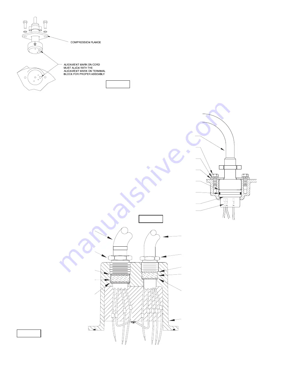
Refi ll with cooling oil as outlined in paragraph 1.4. Position
conduit box and square ring over opening. Place lockwashers
on cap screws, apply Loctite to cap screws threads and
torque to 16 ft lbs. Remove gland nuts, friction rings, and
grommets from conduit box inspect and replace if required.
(See Figure 7) Insert one friction ring, grommet, one friction
ring and gland nut into conduit box for power cable. For
control cable (if used), insert grommet, friction ring and gland
nut. Torque gland nuts to 15 ft. lbs to prevent water leakage.
Terminal Block Design:
Power/Control Cable - Refi ll the cooling oil as outlined
in paragraph 1.4. Make wire connections as outlined in
paragraph 3.3. Insert femail end of cord plug into housing
bore aligning timing mark with hole in termail block, (See
Figure 6). Compress cord plug with compression fl ange by
tightening hex bolts into the motor housing. Torque to 132 in-
lbs.
FIGURE 6
FIGURE 7
GLAND NUT
POWER CORD
FRICTION RING
GROMMET
FRICTION RING
GLAND NUT
SENSOR CORD
FRICTION RING
GROMMET
FRICTION RING
CONDUIT BOX &
CABLE ASSEMBLY
FIGURE 8
POWER CORD
CAP SCREW
LOCK WASHER
COMPRESSION FLANGE
RETAINING RING
O-RING
TERMINAL BLOCK
TERMINAL


