background image

5

TABLE 1 - COOLING OIL - Dielectric

SUPPLIER

GRADE

Sohio / Standard

SE 40, Energol HL22 or HL32

Shell

Turbo Oil 32

Texaco

Rando HD32, 522

Sun Petroleum

Supar 110, Sunvis 816WR, 911 or 916

Mobile

D.T.E. Oil Light or Rubrex 200

G&G

Circu Oil 22

Allegheny Petroleum

Altrapar 22

Woco

Premium 100

Caution! - Pressure builds up extremely 
fast, increase pressure by “tapping” air 
nozzle. Too much pressure will damage 
seal. Do Not exceed 10 P.S.I. in motor 
housing.

2) Impeller and Volute Service:
2.1) Disassembly and Inspection:

To clean out volute, disconnect power, remove hex nuts and 
lockwashers, vertically lift motor and seal assembly from 
volute. Clean out body if necessary. Clean and examine 
impeller for pitting or wear, replace if required. Inspect square 
ring and replace if cut or damaged. If impeller requires 
replacing, remove jam nut and washer, by placing a fl at 
screwdriver in the slot of the end of the shaft to hold the shaft 
stationary while unscrewing the impeller. Once impeller is 
removed, remove pull washer and exclusion seal if damaged 
or cut.

2.2) Reassembly:

Position exclusion seal on shaft until it seats against the 
stationary portion of seal. Place pull washer on shaft until it 
seats against exclusion seal. To install impeller, apply a thin 
fi lm of oil to motor shaft and slide impeller straight onto shaft, 
keeping keyways lined up, drive key into keyway. Locate 
washer, apply Loctite to shaft threads, thread hex nut to shaft 

and torque to 40 ft. lbs. Rotate impeller to check for binding. 
Position o-ring on volute fl ange and position impeller and 
motor housing assembly over studs and onto volute. Apply 
thread locking compound to each stud. Thread nut onto studs 
and torque to 20 ft. lbs. Check for free rotation of motor and 
impeller.

3) Motor, Bearing and Seal Service
3.1) Disassembly and Inspection:

To examine or replace the motor, bearing and shaft seal, 
disassemble volute and impeller as outlined in paragraph 2.1. 
Drain oil from motor as outlined in paragraph 1.2.

Position unit upright, using blocks to avoid resting unit on 
shaft. After removal of cord motor housing remove cable 
lead wires from motor lead wires and temperature sensor 
wires (if equipped) from sensor cord, by disconnecting wire 
connectors. Also disconnect ground screw from motor. 
The wiring connections should be noted to insure correct 
connections when reassembling.

Motor - 

Remove the motor bolts and lift motor stator from 

motor rotor and seal plate. Unscrew conduit bushing from 
seal plate and lift motor rotor, shaft, bearing, rotating portion 
of seal, washer and conduit bushing from seal plate.

Inspect windings for shorts and check resistance values. 
Check rotor for wear, if rotor or the stator windings are 
defective, the complete motor must be replaced. To test 
the temperature sensor (if equipped), check the continuity 
between the black and white wires. If found to be defective 
contact a motor service station or Barnes Service 
Department. Check motor capacitor on single phase units 
and replace if defective.

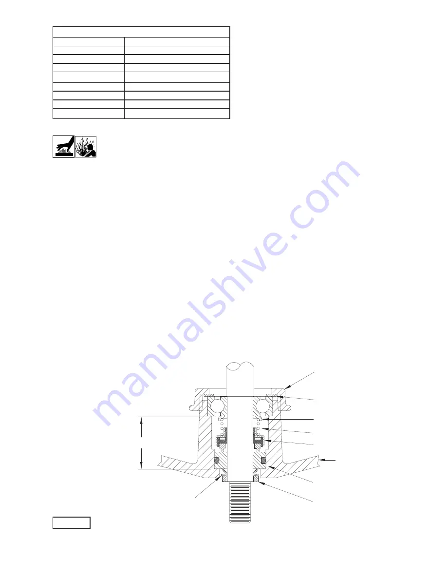
FIGURE 2

SEAL ASSEMBLY

RETAINING RING

SEAL PLATE

SPRING

ROTATING MEMBER

STATIONARY

CONDUIT BUSHING

WASHER

PULL WASHER

EXCLUSION SEAL

MOTOR END

(INBOARD END)

PUMP END

(OUTBOARD END)

Summary of Contents for 130182

Page 1: ...stems reserves the right to change product without prior written notification 420 Third Street 83 West Drive Brampton Piqua Ohio 45356 Ontario Canada L6T 2J6 Phone 937 778 8947 Phone 905 457 6223 Fax 937 773 7157 Fax 905 457 2650 www cranepumps com Form No 130186 Rev C Series 3SE HD Series 3SE L 3 HP 3450 RPM 60 Hz Series 3SE L 3 HP 1750 RPM 60 Hz Series 4SE SS 5 HP 3450 RPM 60 Hz Series 4SE SS 2 8...

Page 2: ...anual 088688 Other brand and product names are trademarks or registered trademarks of their respective holders Barnes is a registered trademark of Crane Pumps Systems Inc 1999 2002 11 03 6 05 4 06 9 06 2 07 Alteration Rights Reserved Seal Repair Kit P N 130182 Service Kit P N 130209 PARTS INCLUDED IN KIT QTY PART NO DESCRIPTION 1 017026 O Ring 1 062641 Pull Washer 1 061829 V Ring 2 033730 Square R...

Page 3: ...NOT insert fingers in pump with power connected Always wear eye protection when working on pumps Make sure lifting handles are securely fastened each time before lifting DO NOT operate pump without safety devices in place Always replace safety devices that have been removed during service or repair Secure the pump in its operating position so it can not tip over fall or slide DO NOT exceed manufact...

Page 4: ...using to 10 P S I Use soap solution around the sealed areas and inspect joints for air bubbles If after five minutes the pressure is still holding constant and no bubbles are observed slowly bleed the pressure and remove the gauge assembly Replace oil as described in section 1 4 If the pressure does not hold then the leak must be located and repaired Pumps that have NOT been disassembled Motor Hous...

Page 5: ... binding Position o ring on volute flange and position impeller and motor housing assembly over studs and onto volute Apply thread locking compound to each stud Thread nut onto studs and torque to 20 ft lbs Check for free rotation of motor and impeller 3 Motor Bearing and Seal Service 3 1 Disassembly and Inspection To examine or replace the motor bearing and shaft seal disassemble volute and impell...

Page 6: ...O NOT use grease shaft bullet and inner surface of bellows on rotating member see Figure 4 with lapped surface of rotating member facing outward slide over bullet and onto shaft using seal pusher making sure spring is seated in retaining ring and spring is lined up on rotating member and not cocked or resting on bellows tail Important It is EXTREMELY important to keep seal faces clean during assem...

Page 7: ... 5 L3 L2 L1 G T6 T5 T4 T3 T9 T8 T7 T2 T1 G THREE PHASE 200 230 VOLT AC MOTOR LEADS GRN G 1 2 3 GRN G WHT BLK RED 1 2 3 4 4 T2 T1 G L2 L1 G MOTOR LEADS CAPACITOR GRN BLK G 1 WHT 3 2 4 TERMINAL BLOCK GRN BLK G 1 WHT 3 2 4 SINGLE PHASE 230 VOLT AC T9 T6 T8 T5 T7 T3 T4 T2 T1 G L3 L2 L1 G BLK THREE PHASE 460 VOLT AC TERMINAL BLOCK GRN G G GRN MOTOR LEADS 2 1 3 1 2 RED WHT 3 4 4 TERMINAL BLOCK P2 P1 G S...

Page 8: ...ng Repeat terminal block installation for sensor cord if equipped 3 4 Conduit Box and Cord Assembly Conduit Box Design Refill with cooling oil as outlined in paragraph 1 4 Position conduit box and square ring over opening Place lockwashers on cap screws apply Loctite to cap screws threads and torque to 16 ft lbs Remove gland nuts friction rings and grommets from conduit box inspect and replace if r...

Page 9: ...erformance specifications must be in writing and such writing must be signed by our authorized representative Due to inaccuracies in field testing if a conflict arises between the results of field testing conducted by or for user and laboratory tests corrected for field performance the latter shall control RECOMMENDATIONS FOR SPECIAL APPLICATIONS OR THOSE RESULTING FROM SYSTEMS ANALYSES AND EVALUATIONS...

Page 10: ...ent To Insure That Employees Will Not Be Exposed To Health Hazards In Handling Said Material All Applicable Laws And Regulations Shall Apply IMPORTANT WARRANTY REGISTRATION Your product is covered by the enclosed Warranty To complete the Warranty Registration Form go to http www cranepumps com ProductRegistration If you have a claim under the provision of the warranty contact your local Crane Pump...

Reviews: